
Troubleshooting guide

1BHFt%3*45&&.7BQPSMPHJD*OTUBMMBUJPOBOE0QFSBUJPO.BOVBM
4UFQo'JFMEXJSJOH
$POUSPMJOQVU
Connect control input signal wiring by inserting wires into
Terminal P11 (labeled 24, RH, and ground) per the wiring
diagram on the next page. Tighten screws; maximum torque is
3 in-lb (0.34 N-m).
Allowed inputs at Terminal P11 include:
t 3)USBOTNJUUFSPSEFXQPJOUUSBOTNJUUFS
Transmitters provide a signal proportional to the RH or dew
point being measured. All transmitters provided by
DRI-STEEM are two-wire devices using a 4 to 20 mA signal.
t %FNBOETJHOBMCZPUIFST
Demand signals are sent to the Vapor-logic4 board from another
control system such as a building automation system. These
systems have their own RH or dew point transmitters, calculate
required humidifier output, and send a demand signal to the
humidifier to create steam at a percentage of that humidifier’s
capacity. Demand signals are typically 0-10 VDC or 4-20 mA,
but may also come from a DDC signal via Modbus, BACnet, or
LonTalk.
A humidistat also delivers a demand signal to the humidifier,
but it is not typically used with Vapor-logic4.
Humidistats provide either on-off control or modulating control.
DRI-STEEM humidistats are powered by a 24 VDC supply
provided by the Vapor-logic4 control board.
When using modulating control, the signal from a humidistat
directly controls the amount of output from the humidifier.
Notes:
t 4FF'JHVSF
t 'PSNPSFJOGPSNBUJPOBCPVUDPOUSPMJOQVUTJHOBMUZQFTBOE
operation, see “Control input signals” on Page 14.
t 4FFi.PECVT#"$OFU-PO5BMLJOUFSPQFSBCJMJUZwPO1BHF
for more information about input signals.
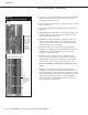
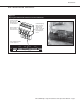
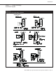
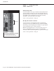
Figure 12-1:
Terminal P11
Terminal P11:
24VDC = Power to space RH sensor
RH = Space RH input (RH transmitter, dew point
transmitter, humidistat, or demand signal by
others) (4-20 mA or 0-16 (typ. 0-10) VDC input
= Ground for demand signal by others
Terminal P11
Note:
If you do not know which control
components were ordered with your system,
contact DRI-STEEM or connect your keypad/
display to the Vapor-logic4 board per the
instructions on Page 19. Go to the Setup
menu per the instructions on Page 28 to
view system parameters that were factory
configured as ordered.
Installation