
Installation guide


DRI-STEEM Vapor-logic
3
*OTUBMMBUJPOBOE0QFSBUJPO.BOVBMt1BHF
(FOFSBMXJSJOHQSPDFEVSFT
continued
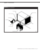
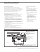
Figure 21-1:
Vapor-logic
3
probe wiring
Brown or black, top probe rod (full water condition)
Orange or white, middle probe rod (refill water condition)
Purple or red, bottom probe rod (low water condition on standard
water models or low water cutoff switch on DI water models)
OM-VL3-11
Low water cutoff switch
on DI water models
Notes:
t 1SPCFXJSJOHTIPVMECFHBVHFNN
2
) stranded wire run in conduit independent of
line voltage wiring
t *.1035"/5%POPUVTFTIJFMEFETDSFFOFEDBCMFGPSQSPCFXJSJOH
t 8IFOXJSJOHFYUFSOBMFMFDUSJDBMDPOOFDUJPOTUPIVNJEJTUBUT
room/duct humidity and temperature transmitters, or control
signal input connections from a building control system, use
18-gauge (1 mm
2
) (minimum) plenum-rated, twisted-pair wire,
with cable shield (screen) wire for grounding.
t 3FUVSOBMMTIJFMEFETDSFFOFEDBCMFDPOOFDUJPOTUPUIFDPOUSPM
cabinet for grounding. Do not ground shield (screen) at the
device end.
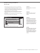
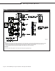
t 6TFHBVHFNN
2
) stranded wire run in conduit (see figure
below) for probe and low water cutoff wiring.
IMPORTANT:
Do not use shielded (screened) cable for
probe wiring.
IMPORTANT:
Locate the control cabinet so that wire
lengths are 50' (15 m) or less to the
humidifier.
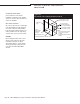
IMPORTANT:
When routing modular cable inside the
control cabinet, route cable away from
all power wiring and connect the male
modular plug into the Vapor-logic
3
printed
circuit board-mounted female modular
receptacle, J2. Push the male plug in until
you hear a “click.” (The cable should be
plugged into the keypad/display as well.)
CAUTION:
When making penetrations in the control
cabinet, protect all internal components
from debris and vacuum out cabinet
when finished. Failure to comply with this
warning may damage sensitive electronic
components and void the DRI-STEEM
warranty.
VL3_IOM.pdf 25 11/19/2009 9:11:11 AM