
Installation guide


DRI-STEEM Vapor-logic
3
*OTUBMMBUJPOBOE0QFSBUJPO.BOVBMt1BHF
Main control board connections,
continued
Important note about J14/J17, J15/J18, and J16/J19
All external wiring connection diagrams show shunts on J14/J17,
J15/J18, and J16/J19. The shunts and appropriate software are
configured by DRI-STEEM based on original customer orders. Field
modification of these shunts requires control input modification:
See Page 31, “Changing control input.”
++ These jumper pins determine the type of analog input
signal that is read at the RH sensor input (terminals 21
through 23, terminal block J26). The three jumper positions
are summarized below:
t 33FTJTUBODFUPPINSBOHF
– Used with on-off humidistats, staging switches, PE
switches
– Used with analog 0 to 150 ohm input devices
(pneumatic transducer or humidistat)
t *$VSSFOUUPN"SBOHF
– Used with any humidity sensor with 4 to 20 mA
output
– Used with any computer or building automation
system with 4 to 20 mA output
– Internal resistance is 249 ohms
t 77PMUT%$UPWPMUSBOHF
– Used with any DC voltage control signal, the default
input signal is 0 to 10 VDC
++ These jumper pins determine the type of analog input
signal that is read at the duct high limit RH input
(terminals 24 through 26, terminal block J27). The jumper
positions (R, I, and V) are identical to those specified for
J14/J17.
++ These jumper pins determine the type of analog input
signal that is read at the window temperature sensor input
(terminals 27 through 29, terminal block J28). The jumper
positions (R, I, and V) are identical to those specified for
J14/J17.
J20 Wire terminal connector supplies 24 VAC control voltage to
the fill valve via terminals 1 and 2 and to the drain valve via
terminals 3 and 4.
J21 Wire terminal connector supplies 24 VAC control voltage
to the power contactor (power vent relay on GTS) via
terminals 5 and 6 and to the SDU or Area-type fan relay via
terminals 7 and 8.
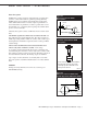
Figure 13-1:
Vapor-logic
3 main control board detail
VL3-OM-010B
J19 J16
R
I
V
R
I
V
J18 J15
R
I
V
J17 J14
Jumper connectors:
R = Resistive input
I = Current input
V = Voltage input
VL3_IOM.pdf 17 11/19/2009 9:11:06 AM