APPLICATION NOTE Atmel AT02597: ZigBee PRO Packet Analysis with Sniffer Atmel MCU Wireless Features • ZigBee® Protocol Analysis with Industry-standard sniffing tools such as Luxoft’s BitCatcher, Wireshark and Perytons • Provides instructions and examples on using the sniffer to analyze and debug network behavior Description Monitoring Wireless network activity in ZigBee networks is essential in understanding the behavior and traffic patterns of the network.
Table of Contents 1. Overview .............................................................................................. 3 1.1 1.2 1.3 The Wireshark Capture Interface from Atmel Gallery........................................ 3 1.1.1 Setup Information ............................................................................... 4 BitCatcher ......................................................................................................... 5 1.2.1 Setup Information ..............................
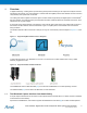
1. Overview In ZigBee networking, a sniffing tool is important during development and testing for the capture and analysis of frames exchanged in the network. It is more significant in networks that have ZigBee products from different vendors to test and verify that they inter-operate with one another. The sniffing tool shall be capable of real-time capture of frame formats supported by the ZigBee protocol and the IEEE® 802.15.4 standard.
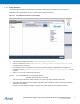
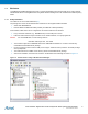
1.1.1 Setup Information To setup the capture session using Wireshark, download the Atmel Wireshark Interface from Atmel Gallery [7]. Wireshark version Wireshark-win32-1.8.0 or lesser shall be installed on the PC [8]. Figure 1-3. Atmel Wireshark Interface in Atmel Gallery. • The package is installed in directory \Atmel\AtmelWiresharkFirmware • Follow the instructions in the Readme_Important_Atmel_Wireshark_Sniffer_Interface.
1.2 BitCatcher Luxoft BitCatcher ZigBee Network Analyze tool is a simple and flexible protocol analyzer that can be used to analyze standard IEEE 802.15.4 and ZigBee frames using Atmel hardware sniffing tools in the sub-GHz and 2.4GHz frequency bands. 1.2.1 Setup Information The sniffer PC tool can be downloaded from [3]. The package also comes with the firmware files and drivers for the supported sniffer hardware: • • Atmel AVR® RZUSBSTICK Dresden Elektronik deRFusb-23E00 (2.
1.3 Perytons Network Analyzer The Perytons Analyzer is a powerful sniffing tool with support for Atmel sniffer hardware platforms for both 2.4GHz and sub-GHz IEEE 802.15.4 bands. This application note gives only a brief overview of its features and analysis of data captures with the Perytons Network Analyzer. Further information can be found at [9].
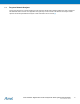
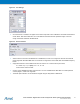
2. Sniffer Capture Session Setup This chapter shows the user how to setup a sniffer capture session after the installation of the hardware driver and the sniffer tool in the PC has been done successfully. 2.1 Wireshark Capture Interface • Open Wireshark_Sniffer_Interface.exe from \Program Files\Atmel\AtmelWiresharkFirmware • From the Sniffer Port column, select the Sniffer port number and click Open as shown in Figure 2-1 Figure 2-1. COM Port Selection.
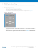
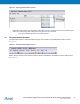
Figure 2-2. Starting a Sniffer Capture Session. • 2.2 After the capture session is complete, the user can save the capture file for further analysis BitCatcher • Open BitCatcher and add a new sniffer device as shown in Figure 2-3 with the port settings in Figure 2-4 Figure 2-3. Adding a New Sniffer Device.
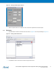
Figure 2-4. Port Settings. • Once the device is created, it will appear in the device drop-down menu in BitCatcher and shall be selected as shown below. After device selection, the connect/Disconnect button shall be pressed to begin or end the usage of the sniffer hardware with BitCatcher Figure 2-5. Device Selection. • After the device connection with BitCatcher is established, the user can configure the Channel and Channel pages supported. Standard IEEE 802.15.4 channels are supported in the 2.
Figure 2-6. Starting the Data Capture Session. • BitCatcher allows users to save the sniffer capture data in the form of .dcf files and it is also possible to open sniffer logs created using other sniffing tools, if the logs are in the .dcf format File->Open log/Save log options serve these purposes. 2.3 Perytons Network Analyzer The Data capture session in Perytons Network Analyzer can be started using the Data Capture button as shown in Figure 2-7. Figure 2-7. Starting the Data Capture Session.
Figure 2-8. Configuring the Capture Parameters. The user can save the capture file using the Save & Continue option shown in Figure 2-8.
3. Configuring Sniffer Preferences For easier viewing and analysis, sniffers GUIs provide multiple filtering options. With the appropriate settings, a complete snapshot of the wireless network can be obtained. This chapter provides information on configuring such preferences in the sniffer GUI. 3.1 Wireshark Capture Interface • Protocols: Wireshark automatically identifies the protocol in use, as all supported protocols are enabled by default, as can be seen in menu option Analyze -> Enabled Protocols.
Table 3-1. Security Levels – NWK and APS – ZigBee Specification. Security level identifier Security level subfield (Table 4.
Figure 3-3. Wireshark Capture Screen Layout. 3.2 BitCatcher • Protocols: By default, BitCatcher is automatically able to parse the following protocol packets: • IEEE 802.15.4 MAC • ZigBee PRO (Network, ZDO and APS layers) • ZigBee Public Profiles such as ZigBee Smart Energy, Home Automation, and Light Link It is not possible to explicitly disable any of the above protocols in BitCatcher, although it is possible to enable or disable packet views of various ZigBee PRO layers (NWK, APS and ZCL).
The security level shall be set as per the ZigBee specification, Table 3-1 is taken from the ZigBee specification document and lists the supported security levels. ZigBee Light Link (ZLL) security keys used for inter-PAN data exchange can also be configured in this sniffer using menu option Window -> Sniffer -> Preferences -> ZLL security. It is possible to add multiple keys, edit or remove existing keys as shown in Figure 3-4.
The security level shall be set as per the ZigBee specification, Table 3-1 is taken from the ZigBee specification document and lists the supported security levels. • User Interface Options: It is possible to customize viewing options in Perytons • The tool provides different viewing options such as the Time view, Network view, Message view, Statistics, and Message Tree view. The user can enable or disable views using menu option Windows • Add Columns to the packets log panel (e.g.
4. Analyzing Data Traffic in ZigBee PRO Networks This chapter provides examples of common interaction in ZigBee PRO networks that shall aid the user to look closely into various fields of the frame and is not aimed at covering all scenarios that fall under ZigBee specification. Explaining the meaning of all the fields used in a ZigBee frame is outside the scope of this application note and shall be looked up in the ZigBee specification [6].
When a node starts up, it does network discovery by performing an active scan over the channels specified in the CS_CHANNEL_MASK parameter in BitCloud. A beacon request is sent as seen in packet #4 in Figure 4-2. Upon reception of a beacon request frame, routers and coordinators already present in network automatically respond with a beacon frame. The joining node filters a potential parent based on the settings in the beacon packet received. Figure 4-2.
Figure 4-4. Beacon Payload. Table 4-1. Config. Server Parameters Affecting Beacon Payload. Capability info sub-field Config. server parameter routerCapacity CS_MAX_CHILDREN_ROUTER_AMOUNT edCapacity CS_MAX_CHILDREN_AMOUNT A joining device indicates its capability information in the MAC association request it sends to its potential parent as shown in Figure 4-5 and Table 4-2. Figure 4-5. Capability Information in a MAC Association Request. Table 4-2. Config.
Without a proper setting of the CS_UID parameter, a node tries to repeatedly join the network CS_ZDO_JOIN_ATTEMPTS times unsuccessfully. Figure 4-6. Node Tries to Join Network Without Proper Setting of IEEE Address. 4.3 Network Rejoin with and without PDS There are multiple join options that can be configured using BitCloud as mentioned in [1].
Figure 4-7. Node Joins Network Via Rejoin Procedure with PDS Not Used in Application. The Persist Data Server (PDS) Component provides useful API to store networking parameters to persistent memory to retain them over device resets. See section PDS in [1]. With PDS APIs used in application, the node сan be configured to come back into the network without performing over-the-air rejoin procedure. In Figure 4-8, the node with short address 0x0001 joins network via rejoin from packet #3.
Figure 4-8. Node Joins Network Via Rejoin Procedure with PDS Used in Application. The silent rejoin is very useful when nodes are reset after a battery change, or after a mains-powered network has reset after a power outage. The nodes come back into the network seamlessly and can route packets, with their networking tables restored from Persistent memory to RAM. Packet #9 shows a device announcement frame. This broadcast frame is sent by a device after it has properly authenticated into the network.
Figure 4-9. Self-Leave of Node With Short Address 0x0001 and Extended Address 0x02ULL. Figure 4-10. Parent Node 0x0000 Sends a ZDP Request Requesting Child 0x0001 to Leave. It is possible to configure options such as rejoin, removal of children in the leave request. 4.5 Network Link Status Frame NWK link status frames are sent by routers and coordinator so that neighboring nodes can maintain information on the link costs required for routing.
Figure 4-11. Header Information in a NWK Link Status Frame. Table 4-3. 4.6 Config. Server Parameters Relevant to NWK Link Status. Information Config. server parameter Neighbor Table size CS_NEIB_TABLE_SIZE Number of missed link status frames to remove an entry from neighbor table CS_NWK_MAX_LINK_STATUS_FAILURES Multicast Broadcasting a message to a group of nodes involves creating a group table entry for a specified end-point and group ID. Refer to Section 6.4.
Figure 4-12. Multicast Sub-Field – NWK Header. In response to #34, group member node 0x31BC responds with APL data on end-point 0xF0 whereas node 0x0BDD is a non-member and so does not respond. 0x0BDD is then added to the group and so responds with APL data on end-point 0xF0 in #59. 4.7 Fragmentation When APL data packets greater than the maximum size of the APL payload needs to be sent, the stack fragments the entire data into blocks. The fragmentation concept is explained in Section 6.
Figure 4-14. Fragmentation – Example. As per ZigBee specification, the first fragment is sent with the block number as the total number of blocks comprising the entire APL data, as seen in Figure 4-14. The subsequent fragments have block numbers starting from 1 onwards up to maximum transmission window size. The receiving node sends an APS Acknowledgment frame when all blocks in the transmission window have been received. Table 4-4. 4.8 Config. Server Parameters Affecting Data Transmission.
Figure 4-15. Status Field in APS Update Device Command. Trust Center sends the APS Tunnel command frame in #39. The Tunnel command frame will contain the secured frame to be sent to the destination, in its payload. #43 shows the APS Transport Key command frame sent from the router parent to the newly joined end-device. It includes the key sequence number and the active network key.
5. Analyzing Data Traffic in ZigBee PRO Public Profile Networks Networks based on ZigBee PRO Public Profiles such as ZigBee Smart Energy, Home Automation, Light Link employ specific join, security and data exchange schemes. The implementation details of the reference applications can be found in [5]. This chapter provides sniffer data analysis of example sniffer logs taken using [5].
This sub-field shall be set to TRUE for all manufacturer-specific extensions to ZCL specification (addition of new attributes, commands to existing clusters and addition of new clusters). 5.1.3 Commands The HA reference application demonstrates usage of ZCL specified commands. In #189, an addGroup command is sent from the Dimmer switch to the Light for the Group ID, defined in the application.
The first part of the Touchlink process is the scanning done on the channel set (primary and if required, secondary) to search for devices in the vicinity. To monitor activity on multiple channels at the same time, it is necessary that the sniffing tool is capable of multichannel capture and the number of hardware sniffing tools used shall equal the number of channels to be monitored. The log, ZLL_CL_CSR.wrk, was captured using a Perytons M-series Network Analyzer.
6. Example Application Scenarios The zip package that comes with this application note includes sniffer logs with the example application scenarios below. This will help the user to understand the packet exchange in the following cases that are not directly covered by the reference applications in the BitCloud SDK. These scenarios require the user to modify the application to see and understand the described scenarios. 6.
Figure 6-1. Link Key Establishment Between Two Routers Trust Center uses the Transport Key command to send the link key to both the routers. The link key is applied in further data exchange between the routers. #3678 uses this link, as seen in the packet view -> apsMic-> Key. 6.3 ZLL – ZHA Interoperability It is possible for a ZigBee Home Automation device to join a ZLL network. The sniffer log, ZLL_HA_S_L_GW.dcf, shows an occupancy sensor device joining a ZLL network at packet #305.
7. References [1]. Atmel AVR2050: BitCloud Developer Guide [2]. RZ600 [3]. BitCatcher [4]. AVR2015: RZRAVEN Quick Start Guide [5]. BitCloud Profile Suite [6]. ZigBee Standards Documentation [7]. Atmel Wireshark Interface - Atmel Gallery [8]. Wireshark [9]. Perytons Network Analyzer [10].
8. Revision History Doc. Rev.
Atmel Corporation Atmel Asia Limited Atmel Munich GmbH Atmel Japan G.K. 1600 Technology Drive Unit 01-5 & 16, 19F Business Campus 16F Shin-Osaki Kangyo Building San Jose, CA 95110 BEA Tower, Millennium City 5 Parkring 4 1-6-4 Osaki, Shinagawa-ku USA 418 Kwun Tong Road D-85748 Garching b. Munich Tokyo 141-0032 Tel: (+1)(408) 441-0311 Kwun Tong, Kowloon GERMANY JAPAN Fax: (+1)(408) 487-2600 HONG KONG Tel: (+49) 89-31970-0 Tel: (+81)(3) 6417-0300 www.atmel.