
User's Manual
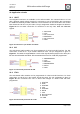
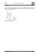


Table Of Contents
- 1. Overview
- 2. Applications
- 3. Features
- 4. Technical data
- 5. Mechanical size
- 6. Soldering profile
- 7. Pin assignment
- 8. PCB design
- 9. Clock
- 10. Application circuits
- 11. Programming
- 12. Pre-flashed firmware
- 13. Adapter boards
- 14. Radio certification
- 15. Ordering information
- 16. Packaging dimension
- 17. Revision notes
- 18. References

User Manual
Version 1.1c
2013-07-01
OEM radio modules deRFmega
www.dresden-elektronik.de
Page 45 of 52
LNA
The LNA could be used to amplify the received signal. Please regard the manufacturer’s
datasheet for a proper design. The control could be done by DIG4 signal. Refer to
Section 7.2.1 for more information.
RF switch for antenna diversity
The switch must have 50 Ω inputs and outputs for the RF signal. It is possible to use a
separate switch with 2 inputs and 2 outputs or use another (third) switch following the switch
required for the PA/LNA. Antenna diversity switching could be controlled via DIG1. Refer to
Section 7.2.1 for more information.
Certification
The customer has to ensure, that custom front-end and antenna diversity designs based on
the radio module deRFmega128-22M10 will meet all national regulatory requirements of the
assignment location and to have all necessary certifications, device registration or
identification numbers.
For long range applications we recommend the use of the deRF-mega128-22M12 radio
module which already includes PA, LNA, BPF, RF switches and antenna diversity. This
module will be provided by dresden elektronik with certified reference designs for EU and US
applications that meet all regulatory requirements and reduce custom design costs.