
User's Manual
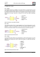
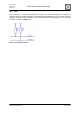


Table Of Contents
- 1. Overview
- 2. Applications
- 3. Features
- 4. Technical data
- 5. Mechanical size
- 6. Soldering profile
- 7. Pin assignment
- 8. PCB design
- 9. Clock
- 10. Application circuits
- 11. Programming
- 12. Pre-flashed firmware
- 13. Adapter boards
- 14. Radio certification
- 15. Ordering information
- 16. Packaging dimension
- 17. Revision notes
- 18. References

User Manual
Version 1.1c
2013-07-01
OEM radio modules deRFmega
www.dresden-elektronik.de
Page 43 of 52
10.4. TWI
The connection of external peripherals or sensors via Two-Wire-Interface is possible by
using the TWI clock signal PD0/SCL and TWI data signal PD1/SCA. The necessary pull-up
resistors must be placed externally on the base board. We recommend the use of 4.7 kΩ
resistors as shown in Figure 39.
Figure 39: Two-Wire-Interface