
User's Manual
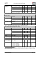

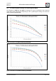
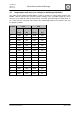

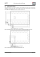

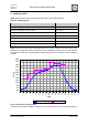
Table Of Contents
- 1. Overview
- 2. Applications
- 3. Features
- 4. Technical data
- 5. Mechanical size
- 6. Soldering profile
- 7. Pin assignment
- 8. PCB design
- 9. Clock
- 10. Application circuits
- 11. Programming
- 12. Pre-flashed firmware
- 13. Adapter boards
- 14. Radio certification
- 15. Ordering information
- 16. Packaging dimension
- 17. Revision notes
- 18. References

User Manual
Version 1.1c
2013-07-01
OEM radio modules deRFmega
www.dresden-elektronik.de
Page 20 of 52
6. Soldering profile
Table 6-1 shows the recommended soldering profile for the radio modules.
Table 6-1: Soldering Profile
Profile Feature
Values
Average-Ramp-up Rate (217°C to Peak)
3°C/s max
Preheat Temperature 175°C ±25°C
180 s max
Temperature Maintained Above 217°C
60 s to 150 s
Time within 5°C of Actual Peak Temperature
20 s to 40 s
Peak Temperature Range
260°C
Ramp-down Rate
6°C/s max
Time 25°C to Peak Temperature
8 min max
Figure 13 shows a recorded soldering profile for a radio module. The blue colored line
illustrates a temperature sensor placed next to the soldering contacts of the radio module.
The pink line shows the set temperatures depending on the zone within the reflow soldering
machine.
40
60
80
100
120
140
160
180
200
220
240
260
280
0
20
40
60
80
100
120
140
160
180
200
220
240
260
280
300
320
340
360
t [s]
T [°C]
Measured Temp. Zone Temp.
Figure 13: Recorded soldering profile
A solder process without supply of nitrogen causes a discoloration of the metal RF-shielding.