
User's Manual
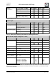
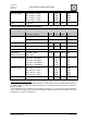

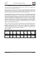
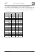


Table Of Contents
- 1. Overview
- 2. Applications
- 3. Features
- 4. Technical data
- 5. Mechanical size
- 6. Soldering profile
- 7. Pin assignment
- 8. PCB design
- 9. Clock
- 10. Application circuits
- 11. Programming
- 12. Pre-flashed firmware
- 13. Adapter boards
- 14. Radio certification
- 15. Ordering information
- 16. Packaging dimension
- 17. Revision notes
- 18. References

User Manual
Version 1.1c
2013-07-01
OEM radio modules deRFmega
www.dresden-elektronik.de
Page 15 of 52
4.3. Output power and duty cycle settings for deRFmega128-22M00
The radio module deRFmega128-22M00 must observe the duty cycle settings to be
compliant with all FCC regulatory requirements.
The requirements are a duty cycle which is ≤15% for channel 26 operation and ≤36% for the
remaining channels. The duty cycle is related to a period of 100ms, where the given value
defines the TX-ON time. That means, the maximum allowed TX-ON time is 15ms within a
period of 100ms for channel 26 and 36ms for all other channels respectively.
The available default firmware for the radio modules is a ‘Wireless UART’ (WUART) that
transmits wireless data inputs from one node to another. The WUART packets length
including overhead ranges between of 12 and 127 bytes. All radio protective systems like
automated acknowledgement, CSMA-CA and frame-retry are activated. Therefore sending a
packet with maximum length takes approximately 4ms to from start to end of transmission.
Before each transmission, a fixed delay time of 30ms is defined, to ensure that the available
maximum packet length is used. This optimizes the energy performance of the radio module,
because not every single data input will be transmitted separately. The fixed delay time
cannot be changed by software. By default, the WUART firmware operates at channel 20
which also cannot be changed by the user.
Table 4-7 shows a worst case scenario of data transmission with maximum packet length of
127 bytes. The data input will be buffered within the 30ms delay and then transmitted. The
CSMA-CA wait time is assumed to be zero. Here, the RX-ON time of receiving the
automated acknowledgement after each transmission is ignored. The transition will be
continued until all data inputs are successfully transmitted. Therefore, the resulting duty cycle
is ≤ 12% and fulfills the FCC requirements for all channels.
Table 4-7: Timeline
Data transmission timeline
Operation
State
buffer
input
data
transmit
data
buffer
input
data
transmit
data
buffer
input
data
transmit
data
buffer
input
data
TX State
OFF
ON
OFF
ON
OFF
ON
OFF
…
Duration [ms]
30
4
30
4
30
4
30
…
Time [ms]
0..
30
30..
34
34..
64
64..
68
68..
98
98..
102
102..
132
…