
User's Manual
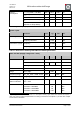
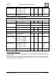

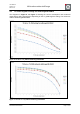
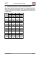

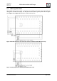

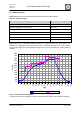
Table Of Contents
- 1. Overview
- 2. Applications
- 3. Features
- 4. Technical data
- 5. Mechanical size
- 6. Soldering profile
- 7. Pin assignment
- 8. PCB design
- 9. Clock
- 10. Application circuits
- 11. Programming
- 12. Pre-flashed firmware
- 13. Adapter boards
- 14. Radio certification
- 15. Ordering information
- 16. Packaging dimension
- 17. Revision notes
- 18. References

User Manual
Version 1.1c
2013-07-01
OEM radio modules deRFmega
www.dresden-elektronik.de
Page 13 of 52
4.1. TX Power register settings for deRFmega128-22M00 and 22M10
The diagrams in Figure 4 and Figure 5 are showing the current consumption and conducted
output power during transmission depending on the TX_PWR register setting. The values are
valid for deRFmega128-22M00 and 22M10.
Figure 4: TX Idd vs. TX_PWR for deRFmega128-22M00 / 22M10
Figure 5: TX Pout vs. TX_PWR for deRFmega128-22M00 / 22M10