
User's Manual


User Manual
Version 01.00
2011-03-31
USB radio sticks deRFusb
dresden elektronik
ingenieurtechnik gmbh
Enno-Heidebroek-Str. 12
01237 Dresden / Germany
Tel.: 0351 – 31 85 00
Fax: 0351 – 3 18 50 10
wireless@dresden-elektronik.de
www.dresden-elektronik.de
Page 17 of 22
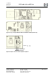
General transceiver description
These single-chip radio transceivers provide a complete radio transceiver interface between
an antenna and a microcontroller.
They comprise the analog radio transceiver and the digital modulation and demodulation in-
cluding time and frequency synchronization and data buffering. The number of external com-
ponents is minimized such that only the antenna, the crystal and decoupling capacitors are
required. The bidirectional differential antenna pins are used for transmission and reception,
thus no external antenna switch is needed.
An internal 128 byte RAM for RX and TX buffers the data to be transmitted or the received
data. Two on chip low dropout voltage regulators provide the internal analog and digital 1.8V
supply.
The transceivers further contain comprehensive hardware-MAC support (Extended Operat-
ing Mode) and a security engine (AES) to improve the overall system power efficiency and
timing.
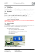
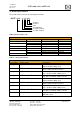
9. Onboard flash (option)
A 2 GByte flash memory to store user defined data is optionally available using the deRFusb-
23E06 and deRFusb-13E06 USB radio sticks.
This flash memory is typically applied as mass storage device for user data. It works like a
Multimedia Card (MMC). Possible data bit modes are 1bit (default) and 4bit.
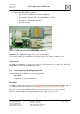
The flash is equipped with a memory controller and has a NAND flash architecture. It com-
plies with e.MMC Specification Version 4.4. The temperature range for safe operation is from
- 25C° to +85C°.