
User Manual


datasheet
Version 0.9
2017-09-13
deRFsamR21E-23S00/-23S20 datasheet
www.dresden-elektronik.de
Page 7 of 36
3. Block diagram
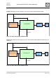
Figure 5-15 shows the block diagram of the radio module deRFsamR21E-23S00.
ATSAMR21E18
4Mbit Serial Flash
Balun &
Harmonic
Filter
Chip
Antenna
SPI
12 GPIO
SPI
VCC
Figure 3-1: Block diagram deRFsamR21E-23S00
Figure 5-2 shows the block diagram of the radio module deRFsamR21E-23S20 with u.FL
connector.
ATSAMR21E18
Balun &
Harmonic
Filter
12 GPIO
U.FL
4Mbit Serial Flash
SPI
SPI
VCC
Figure 5-2: Block diagram deRFsamR21E-23S20