
User Manual


datasheet
Version 0.9
2017-09-13
deRFsamR21E-23S00/-23S20 datasheet
www.dresden-elektronik.de
Page 33 of 36
14. Soldering profile
Table 16-1 shows the recommended soldering profile for the radio modules.
Table 16-1: Soldering Profile
Profile Feature
Values
Average-Ramp-up Rate (217°C to Peak)
3°C/s max
Preheat Temperature 175°C ±25°C
180 s max
Temperature Maintained Above 217°C
60 s to 150 s
Time within 5°C of Actual Peak Temperature
20 s to 40 s
Peak Temperature Range
260°C
Ramp-down Rate
6°C/s max
Time 25°C to Peak Temperature
8 min max
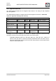
Figure 16-1 shows a recorded soldering profile for a radio module. The blue colored line
illustrates a temperature sensor placed next to the soldering contacts of the radio module.
The pink line shows the set temperatures depending on the zone within the reflow soldering
machine.
Figure 16-1: Recorded soldering profile
A solder process without supply of nitrogen causes a discoloration of the metal RF-shielding.
It is possible that the placed label shrinks due the reflow process.
40
60
80
100
120
140
160
180
200
220
240
260
280
0
20
40
60
80
100
120
140
160
180
200
220
240
260
280
300
320
340
360
T [°C]
t [s]
Measured Temp. Zone Temp.