
User Manual


datasheet
Version 0.9
2017-09-13
deRFsamR21E-23S00/-23S20 datasheet
www.dresden-elektronik.de
Page 26 of 36
10. Programming
The update process of the radio module, the required software and hardware for
programming via SWD interface and the driver installation on different operating systems are
described in this chapter. Currently, the SWD interface is supported by several Atmel and
third party programmers and debuggers like Atmel ICE and Segger J-Link. Other
programmers that support ATSAMR21E18A will work as well.
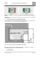
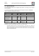
For the programming the standard SWD header is recommended as 10pin 1.27 mm header
as shown in Figure 12-1.
Figure 12-1: Programming header
10.1. Software/Applications
For software development several options are available depending on your needs:
For low-cost embedded wireless applications the MiWi Stack from Microchip supports
the ATSAMR21. More information can be found at http://www.microchip.com/design-
centers/wireless-connectivity/embedded-wireless/802-15-4/software/miwi-protocol
For ZigBee 3.0 home automation projects Microchip offers the ZigBee 3.0 BitCloud
software stack. This stack is platform certified by the ZigBee Alliance. For more
information see
http://www.microchip.com/design-centers/wireless-connectivity/embedded-
wireless/802-15-4/zigbee-3-0
Please contact your local Microchip Sales Representative to get access to the
BitCloud Software Development Kit.
In Atmel Studio the Atmel Software Framework (ASF) offers a big number of
examples for ATSAMR21G18A. It is the same controller in a package with more
GPIO Pins available for the user. Some minor adjustments are necessary to allow the
examples to run on ATSAMR21E18A on this module.
Suitable compilers are GCC (v4.5.2) or IAR Compiler(IAR C/C++ Compiler for ARM v7.80.1)
for example.
Dresden elektronik offers software development services for with comprehensive experience
in ZigBee 3.0 and IEEE 802.15.4 wireless applications.
10.2. Clocks
The controller runs on 8 MHz RC-oscillator by default. Since the internal clock generation is
not very accurate, it is recommended to use the external transceiver oscillator to avoid
problems during communication for example by UART. To change the clock source to the
precise transceiver oscillator (±10 ppm at 25°C) the transceiver has to be configured for
clock output (CLKM) and the clock source at the controller has to be set to „GLCKIN“/“
GCLK_IO[1]“.
During deep sleep operation the clock source is best set to „OSCULP32K“ for minimized
current consumption. Further information can be found in [1].