
User Manual


datasheet
Version 0.9
2017-09-13
deRFsamR21E-23S00/-23S20 datasheet
www.dresden-elektronik.de
Page 23 of 36
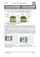
Figure 11-5: Placing in the centre with
antenna
Figure 11-6: Placing in the centre with RF pad
Do not place ground areas below the radio module and near the chip antenna (see Section
11.5 and 11.7).
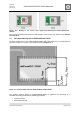
9.7. Recommended layout for deRFsamR21E-23S00
For best performance of the deRFsamR21E-23S00 with chip antenna it is recommended to
place the module at a corner of the PCB according to Figure 11-7.
Figure 11-7 recommended layout for deRFsamR21E-23S00 module
The module antenna design of deRFsamR21E-23S00 is optimized for mounting on a
standard technology PCB with the following properties:
Two-layer board
Board material FR4