
User Manual


datasheet
Version 0.9
2017-09-13
deRFsamR21E-23S00/-23S20 datasheet
www.dresden-elektronik.de
Page 19 of 36
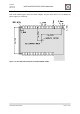
8.1. Signal description
The features of the controller can be mapped to different ports. How to configure the device
for the example configuration is described in this chapter. The serial interface functions are
organized in SERCOM units (Serial Communication Interface). These units consist of
4 Signals and can be mapped to several ports of the microcontroller. The configuration is
shown in Table 10-1.
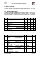
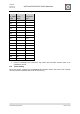
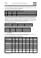
Table 10-1: Pin configuration
Pin
Pad
Function
Config
05
PA14
UART/TXD
SERCOM2/PAD2
06
PA15
UART/RXD
SERCOM2/PAD3
07
PA16
SPI_MISO
SERCOM1/PAD0
08
PA17
SPI_MOSI
SERCOM1/PAD1
09
PA18
SPI_SS
Digital out
10
PA19
SPI_CLK
SERCOM1/PAD3
11
PA24
USBDM
12
PA25
USBDP
17
PA27
GPIO
Digital out
18
PA28
SPI_SS2
Digital out
19
PA30
SWD/SWCLK
20
PA31
SWD/SWDIO
21
-
RESET
23
PA07
ADC/AIN7
24
PA06
ADC/AIN6
25
PA08
I2C/SDA
SERCOM0/PAD0
26
PA09
I2C/SCL
SERCOM0/PAD1
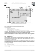
8.2. UART
The UART interface is a commonly used bidirectional interface for communication between
microcontrollers. The transmit (TXD) and receive (RXD) lines have to be connected directly
to the second device. TXD for the host controller is RXD for the client, the other signal works
accordingly.
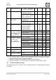
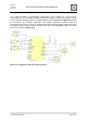
For communication to a host with a different supply voltage domain it is necessary to use a
level-shifter part. We recommend the USB level shifter by dresden elektronik. The level-
shifter can be connected to the custom base board via 100 mil 2 x 3 pin header. The pin
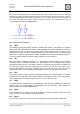
assignment should be designed as below in Figure 10-2. For a UART connection it is
sufficient to use only TXD, RXD and GROUND signals.
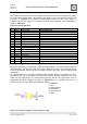
1. PA14/TXD
2. VCC
3. Not connected
4. PA15/RXD
5. Not connected
6. GND
Figure 10-2: 100 mil / 2,54 mm 2 x 3 pin header for UART