
User Manual


datasheet
Version 0.9
2017-09-13
deRFsamR21E-23S00/-23S20 datasheet
www.dresden-elektronik.de
Page 18 of 36
8. Recommended configuration
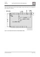
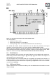
This chapter describes a recommended configuration which enables use of all frequently
used interfaces. The schematic symbol used in this chapter as well as a footprint can be
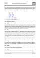
found in dresden elektronik Altium and Eagle libraries (see Section 7.3). Figure 10-1 shows
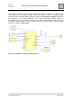
the schematic of a sample application. The sample application provides USB and
incorporates two sensors, a LED, an analogue input measuring the battery voltage and using
the UART interface through a 6-pin header for tracing. This configuration with all common
interfaces is shown in Figure 10-1.
Figure 10-1 configuration with all common interfaces