
Specifications


182011822 Operator’s Manual
the +INPUT COUPLING first be changed to OFF
(precharge) when measuring a new circuit point. This
will safely recharge the AC coupling capacitor in less
than 0.3 seconds. The value of the AC coupling capacitor
is 0.1 laF.
DC and low frequencies are attenuated by the AC
coupling capacitor and the input resistance. With the
ATTENUATOR set to +10, or set to +1 with the INPUT
RESISTANCE set to 1 Mr2, the low frequency cut off
(-3dB point) is approximately 1.6Hz, lower than most
oscilloscopes by a factor of 5. When the input attenuator
is set to +1, the INPUT RESISTANCE may be set to
100 M~, and the -3dB point is 0.016Hz. This extremely
low frequency cut off is often handy in observing low
frequency noise riding on large (up to 400 volts)
voltages.
In the DC mode, the +INPUT connector is connected to
the amplifier either directly or through the input
attenuator, and the AC and DC attenuation are the same.
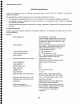
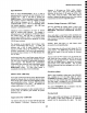
-Input Coupling (AC-OFF-DC-VcoMP)
FROM
PRECISION
100 II Vcoup
VOLTAGE )-
~
v A_
REFERENCE
/ (’O--I
INPUT COUPLING
1 I / / I
CAPACITOR
- INPUT
~ I.~ /-" .........
I
]
CONNECTOR
I I
l r Ac
H
M OF L
("~ I1~
~______.~..~’~O ). AMPLIFIER
I
~ -+lOT 900 KI] ~*10-
ION-
-INPUT
/7/ INPUT
I
~1 Mr1
ATTENUATOR
INPUT
111.1 KI2
RESISTANCE
100 Mfl fl
The -input has the same coupling modes as the +input
plus one additional option, VcoMv (comparison voltage).
The 1822 generates a voltage controlled by the push
buttons above and below the front panel numerical
display. This voltage is called the Precision Voltage
Generator (PVG).
In VCOMP mode, the 1822’s PVG is connected to the
amplifier’s inverting input through an internal filter
designed to eliminate radio and television signal
interference. The 1820 does not have the PVG, but uses
an externally supplied voltage. See Page 2-6 for VcoMv
operation with the 1820.
The 1820/i 822’s amplifier subtracts the voltage applied to
its inverting input from the voltage applied to its non-
inverting input. The 1820/1822 output is therefore zero
whenever these two voltages are equal. For this reason,
the voltage applied to the inverting input is called a
comparison voltage, VcoMP.
VcoMP is often used to make precise measurements of
large signals by comparing the accurately known Vcome
with the unknown signal. It is also used to measure the
actual voltage at any point ofa waveform.
PVG output range is +15.500 volts. The PVG is never
attenuated by the input attenuator. Attenuation of the
+INPUT signal by the -10 input attenuator will cause the
PVG to null out an input voltage up to ±155.00 volts
which is ten times larger than the actual PVG voltage.
When the 1822 is used with attenuating probes that
feature readout, the PVG display is changed to indicate
the voltage at the +INPUT probe tip which will bring the
amplifier output to zero.
The -INPUT connector is not useable when Vcome is
selected.
VDIFF (differential offset voltage) is an instrument mode
rather than a type of input coupling. The VBIFF mode
allows the PVG (or an external source in the 1820)
inject an offset signal into the 1820/1822 while still using
both inputs for full differential operation. This mode can
be used as a position control to move the trace on the
oscilloscope screen in preference to using the
oscilloscope’s position or offset control. The
oscilloscope’s position and offset controls should always
be set to zero so that the 1820/1822’s dynamic range is
properly centered. Operation of the 1820/1822 using the
VD|FF function is the same as VCOMP except for the
following:
¯
The -INPUT remains active, allowing full use of the
1820/1822 as a differential amplifier.
The maximum range of the PVG (1822) or the
external source (1820) is ±10.000 volts in XI Gain
and ±1.0000 volts in X10 to 1000X gain settings.
The effects of the +10 input attenuator and probe
attenuation are the same as when using VCOMP, i.e.
any input attenuation multiplies the effective offset.
The 1822’s PVG display is changed to indicate the voltage
that, if applied between the +INPUT and -INPUT, would
bring the amplifier output to zero. When the 1822 is used
with attenuating probes that feature readout, the PVG
display is scaled to include the effect of probe attenuation.
2-2