
Specifications


Attenuator
1820/1822 Operator’s Manual
Section 2
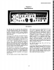
Operating Instructions, Controls, and Indicators
Front Panel
Signals connected to the +INPUT and the -INPUT are
connected either directly to the 1820/1822’s amplifier
inputs or to the input attenuators. The input attenuators
are passive networks which divide each signal by ten.
In ÷1 mode the front panel input connectors are directly
connected to the 1820/1822 amplifier’s differential inputs.
In ÷10 mode each front panel input connector is
connected to a passive 1 Mr2 attenuator. The attenuator
output is connected to the 1820/1822 amplifier’s
corresponding differential input. The signal at each input
is attenuated by a factor of ten.
Gain
The 1820/1822 amplifier gain (amplification) is selectable
XI, XI0, XI00 and XI000. The amplified signal appears
at the rear panel AMPLIFIER OUTPUT connector.
A signal connected to the +INPUT will maintain its
polarity at the output connector. A signal connected to
the -INPUT will be inverted in polarity.
Proper gain is obtained when the 1820/1822 drives a 50
load such as an oscilloscope with input impedance set to
50 fL An oscilloscope with only 1 Mr2 input impedance
available should have a 50 f2 coaxial termination placed
on its input connector. The ! 820/1822 is then connected
to the oscilloscope through the coaxial termination.
The amplifier gain and the input attenuator are
individually selectable to provide versatility. For
example, the comparison voltage range is changed from
+15.5000 to ±155.000 volts by changing the
ATTENUATOR from +1 to ÷10. The overall gain can
still be set to 100, 10, 1 or 0.1 by selecting the GAIN
mode, XI000, X100, XI0 or XI, as desired.
Autobalance is a feature invoked when any gain button is
pushed, even if a different gain is not selected.
Autobalance momentarily sets the INPUT COUPLING
to OFF and determines the offset necessary to set the
output at 0 volts within about 25~tV. During this process
the front panel input coupling controls are unresponsive.
When finished, the INPUT COUPLING returns to its
previous mode. Autobalance usually takes less than one
second. This handy feature allows the operator to DC
balance the 1820/1822 simply by pushing the GAIN
button which is already illuminated. When changing
gains, the Autobalance feature is automatically invoked,
freshly adjusting the amplifier’s DC balance.
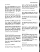
+Input Coupling (AC-OFF-DC)
INPUT COUPLING
CAPACITOR
0.I~ .......
i
+ INPUT
l [ r--- , ¯
CONNECTOR [----11--
7
AC ~11 I+1[
10 900 K~ +10
ATTENUATOR
11111
In the AC mode, the +INPUT is connected through an
AC coupling capacitor to the amplifier input or the input
attenuator. The coupling capacitor retains its charge
when the input is switched to DC, making it possible to
return to the same circuit without the precharge time. But
this also makes it possible to discharge the coupling
capacitor into another circuit under test if its DC voltage
differs by more than approximately 19 volts from the
voltage on the coupling capacitor. Although the
discharge current is limited to about 70mA, this could
damage some circuits. It is therefore recommended that
2-1
In OFF mode, the input connector is disconnected from
the amplifier input, and the amplifier input is connected to
ground. The AC coupling capacitor is connected between
the +INPUT and ground through 1 M~ (either the input
attenuator or the input resistor), independent of the
INPUT RESISTANCE selected. In this mode, the AC
coupling capacitor is quickly charged to the average DC
input voltage. OFF mode is also referred to as precharge
mode. Precharge is particularly useful when planning to
AC couple and measure voltages in excess of 19 volts.
The 1820/1822 input coupling is set to OFF and
connected to the circuit under test. When the +INPUT is
changed from OFF to AC mode, the coupling capacitor is
already charged, and the trace properly centered on the
oscilloscope screen. Additionally, the risk of tripping the
input overload detector and automatically disconnecting
the input is eliminated.