
Specifications
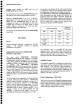


Differential Offset Operation
Leave the 1822 set up as in the previous exercise or set
it up as follows:
+ INPUT
DC
- INPUT
VCOMP
HF-3dB POINT
No lights on (full BW)
LF-3dB POINT
No lights on (DC)
GAIN
Xl0
ATTENUATOR
)1
INPUT RESISTANCE 1M
PRECISION VOLTAGE GENERATOR - 0.0500*
COMPARISON or DIFFERENTIAL COMPARISON
EFFECTIVE GAIN XI0
*approximate
¯ Function Generator output: 50kHz 50mVpk sine
wave. connected to the +INPUT of the 1822.
¯ Oscilloscope: set at 50mV/div (equivalent to 5mV/div
with 1822 at X10 GAIN) and sweep adjusted for 2 to
cycles.
¯ Externally trigger the oscilloscope on the function
generator’s output (same signal as is applied to the 1822’s
+INPUT)
Under these conditions, the negative peak of the display
on the oscilloscope should be very near center screen.
Adjust the value in the Precision Voltage Generator until
the negative peak is at center screen.
Press the Vaw
F
button. This internally applies the output
of the Precision Voltage Generator to a point within the
1822’s amplifier that facilitates a true differential offset.
Also note that the Precision Voltage Generator display
was reset to zero (+ .00000) and the -INPUT coupling
changed. The VcoMP light went out and the OFF light
was lighted. In the line under the Precision Voltage
Generator display (COMPARISON or
DIFFERENTIAL OFFSET), the COMPARISON light
went out and the DIFFERENTIAL light was lighted.
This indicates that the Precision Voltage Generator will
now be applied as a differential offset rather than as a
comparison voltage as in the previous exercise. Both the
+INPUT and the -INPUT inputs are now enabled.
The positive and negative peaks of the waveform
displayed on the oscilloscope are 10 divisions above and
below (respectively) the center line of the display. Push
the button above the digit that is two places right of the
decimal (10mV) in the Precision Voltage Generator until
the positive peak of the waveform appears in the
182011822 Operator’s Manual
oscilloscope’s display. Continue incrementing and
decrementing the digits in the Precision Voltage Generator
until the peak of the waveform is at the center line of the
oscilloscope’s display. The number in the Precision Voltage
Generator display is the value of the waveform’s positive peak
voltage.
Press the + button in the Precision Voltage Generator.
Observe that the negative peak of the signal is now at or near
the oscilloscope display’s center line. By incrementing and
decrementing the digits, the negative peak can be positioned to
the oscilloscope display’s center line. Now the number in the
Precision Voltage Generator’s display is the value of the
waveform’s negative peak voltage.
Change the oscilloscope’s sensitivity from 50mV/div to
10mV/div. Overall sensitivity, including the 1822, is now
ImV/div. Temporarily change the oscilloscope’s input
coupling from DC to GND (or OFF) and re-center the trace
center screen using the oscilloscope’s position control. Return
its input coupling to DC. Now press the XI0 button on the
1822 to invoke its Autobalance function. (Note that pressing
the gain button that is already selected causes the 1822 to
adjust its DC Balance, but does not change its gain.)
Change the Precision Voltage Generator’s reading to again
place the negative peak of the waveform at the oscilloscope’s
center line. Note that the Precision Voltage Generator’s
display more accurately represents the negative peak voltage
of the waveform.
Return the oscilloscope’s sensitivity to 50 mV/div and again
press the 1822’s VDwv button. The VmFF light will go out and
the display on the oscilloscope will be centered about the
center line. Notice that the PVG retains its setting, but the
output of the PVG is not applied to the amplifier. Press the
VD=FF button again and observe that the Precision Voltage
Generator’s output is reapplied internally to the 1822
amplifier.
Following are a few observations on using the differential
offset mode (VDw~) of the 1820/1822:
Both the positive and negative inputs (AC, OFF and DC)
are enabled and the 1820/1822 remains a true differential
amplifier.
The value displayed by the Precision Voltage Generator
indicates a waveform’s differential voltage, with respect
to the -INPUT, as it passes through the oscilloscope
display’s center line. It is very important that the
oscilloscope’s trace be positioned to center screen if an
accurate measurement is to be made using this method.
The voltage applied to the 1820’s EXTERNAL
3-3
e
e
e
e
e
e
e
e
e
e
e
e
e
e
e
e
e
e
e
e
e
e
e
e
e
e
Q
e
e
e
e
e
i