
Specifications


182011822 Operator’s Manual
coupling mode changes to OFF, and the red
OVERLOAD light is turned on.
The 1820/1822 is reset and the OVERLOAD light goes
out when any of the input coupling modes is selected.
When the ATTENUATOR is set to -1, a signal of
approximately ±19 volts will cause the input to draw
current and the OVERLOAD light to come on.
Transients too rapid to he disconnected by the input
coupling relay will draw up to about 70mA of input
current. Inputs in excess of 250 volts may cause
permanent damage to the i 820/1822.
The input is not disconnected when the ATTENUATOR
is set to +10.
Power
Rear Panel
Normal instrument operation is obtained in the ON
position. The instrument reaches its specified
performance in 30 minutes.
PRECISION VOLTAGE GENERATOR
OUTPUT (1822 Only)
The rear panel PRECISION VOLTAGE
GENERATOR OUTPUT BNC connector is a monitor
of the Precision Voltage Generator (PVG). It is the same
voltage that is applied to the -INPUT when the -INPUT
coupling is VCOMe or internally to the 1822 when VDIFF
is selected. The PRECISION VOLTAGE
GENERATOR OUTPUT can be used either to monitor
the PVG with a DVM (digital voltmeter) or as an input
one or more Preamble 1820s or 1822s. There is a
1.59kHz single-pole low pass filter between the PVG
output and the -INPUT which removes radio frequency
interference (RFI). This filter does not attenuate the PVG
signal.
The PVG output is not attenuated by the input attenuator
or probes, whereas the input signal is. Therefore the
effective range of V¢OMP is increased by a factor of 10
when the +10 attenuator is selected or a +10 attenuating
probe is used to attenuate the input signal. The PVG
numerical display reflects the attenuator setting and probe
attenuation when the probe is readout encoded. As an
example, if there are no probes attached, the +10
attenuator is selected and the display is set to read
+155.000, the PVG output will actually be _+15.5 volts.
The decimal in the display will be in the correct location
to indicate the voltage at the PVG output when no probes
are attached and ÷1 attenuator and X1 gain are selected.
The PRECISION VOLTAGE GENERATOR OUT
BNC also presents the same voltage used internally for
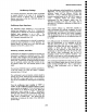
differential offset when VDIFF is selected. Because the
PVG is applied to the amplifier to create a true differential
offset, the relationship between VDIFr and the voltage at
the PVG output BNC changes with the amplifier gain
selection according to the following table:
Maximum
Front Panel Settings
PVG Output
Gain
Atten
VDIFF
X1
+1 +IOV
+IOV
Xl +10 +I00V
+10v
XI0,X100,
+1
+IV +10v
XI000
Xl0,Xi00,
+10 +lOV ±lOV
Xl000
The maximum VDIFF is multiplied by any probe
attenuation factor. When using readout encoded probes
which the 1822 senses, the PVG readout calculates the
effective differential offset at the probe tip. Of course,
both probes must have the same attenuation factor.
Amplifier Output
The amplifier’s output BNC is intended to be used with an
oscilloscope, spectrum analyzer or digitizer having a 50 if2
input resistance. The 1820/1822 output impedance is
50 f2. Without the 50 ~ load, the amplifier gain is twice
the amount indicated on the front panel. Additionally, the
signal presented to an oscilloscope (spectrum analyzer or
digitizer) is as large as ± 10 volts.
Probe Coding Input (1822 Only)
This jack is to be used with Preamble Instruments probes
and other probes that have multiple selectable attenuation
factors. Other manufacturer’s probes with standard probe
coding capability will be properly decoded through the
1822’s front panel +INPUT BNC connector.
2-4