-,~ ~OREAMBLE - VIINSTRUMENTS OPERA TOR’S MANUAL 1820/1822 DIFFERENTIAL AMPLIFIER Revision D August 1999
Table of Contents Section 1 Specifications Introduction ............................................................................. 1- 1 1820/1822 Specifications ........................................................ 1-2 Nominal Characteristics .......................................................... 1-3 Warranted andTypicalCharacteristics .................................... 1-4 Environmental andPhysicalCharacteristics............................
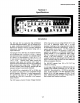
182011822 Operator’s Manual Section 1 Specifications Introduction The 1820 and 1822 are stand-alone high performance 100 MHzdifferential amplifiers. They are intended to act as signal conditioning preamplifiers for oscilloscopes, digitizers and spectrum analyzers, providing differential measurement capability to instruments having only a single-ended input. (PVG)that can be set to any voltage between+15.5 volts (+10 volts in Differential Offset) with 5 1/2 digit resolution.
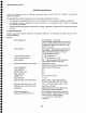
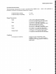
1820/1822 Operator’s Manual 1820/1822 Specifications Except where otherwise noted, the following specifications Differential Amplifiers. apply to model 1820, 1822, 1820-PR2 and 1822-PR2 The specifications are valid for instruments whenthe following conditions have been met: ¯ The instrument is being operated from a powersource which meets the line voltage and frequency specifications.
182011822 Operator’s Manual NominalCharacteristics (continued) Dynamic Ranges Maximum Differential Linear Input: ~ X 1000 Gain, + 1 Attenuator +5 mV j+50 mV X100Gain, +1 Attenuator 1+0.5 V X 10 Gain, - 1 Attenuator I XI Gain, +l Attenuator +5 V I_+50 mV XI000 Gain, +10 Attenuator l X 100Gain, + I 0 Attenuator ¯ +0.5V ~ X 10 Gain, + ! 0 Attenuator +5 V t+50 V XI Gain, +10 Attenuator Maximum CommonMode Input 1+15.
1820/1822 Operator’s Manual WarrantedCharacteristics Warranted characteristics describe parameters which have guaranteed performance. Unless otherwise noted, tests are provided in the PerformanceVerification Procedure for all warrantedspecifications. Gain Accuracy Bandwidth(- 3dB) X1 or XI0 Gain X 100 Gain X 1000 Gain Rise Time (XI or X10 Gain) CommonMode Rejection Ratio (X 1 or X 10 Gain) 70 Hz 100 KHz 1 MHz Precision Voltage Generator Accuracy +1%+ Uncertainty of termination resistance >10 MHz >2.
1820/1822 Operator’s Manual EnvironmentalCharacteristics The Environmental Characteristics are tested to specification MIL-T28800D Class 5. performanceverification of environmentalcharacteristics is required. Temperature Range, operating Temperature Range, non-operating Refer to this specification if 0° - 50° C. -40° - 75° C. Physical Characteristics Height Width Depth Weight Shipping Weight 7.29 cm (2.87") (1820 and 1822 models) 8.75 cm (3.4") (1820-PR2and 1822-PR2models) 21.2 cm(8.
1820/1822 Operator’s Manual Section 2 Operating Instructions, Controls, and Indicators previous mode. Autobalance usually takes less than one second. This handy feature allows the operator to DC balance the 1820/1822 simply by pushing the GAIN button which is already illuminated. Whenchanging gains, the Autobalancefeature is automatically invoked, freshly adjusting the amplifier’s DCbalance.
182011822 Operator’s Manual inverting input. The 1820/1822output is therefore zero wheneverthese two voltages are equal. For this reason, the voltage applied to the inverting input is called a comparison voltage, VcoMP. the +INPUT COUPLINGfirst be changed to OFF (precharge) when measuring a new circuit point. This will safely recharge the ACcoupling capacitor in less than 0.3 seconds. The value of the ACcoupling capacitor is 0.1laF.
1820/1822 Operator’s Manual frequency -3 dB points are 3MHz, I MHz, 300kHz, 100kHz, 30kHz, 10kHz, 3kHz, IkHz, 300Hz and 100Hz. Selections for the lower -3 dB points are 0.1Hz, IHz, 10Hz, 100Hz, lkHz and 10kHz. These filters make it possible to improvethe signal-to-noise ratio whenmaking measurementson microvolt magnitude signals.
182011822 Operator’s Manual The decimal in the display will be in the correct location to indicate the voltage at the PVGoutput whenno probes are attached and ÷1 attenuator and X1gain are selected. The PRECISION VOLTAGE GENERATOR OUT BNCalso presents the same voltage used internally for differential offset whenVDIFFis selected.
182011822 Operator’s Manual Oscilloscope Set the oscilloscope vertical sensitivity to no less than 500mV/div.The most useful range for the oscilloscope deflection factors will be between ! mV/div and 500mV/div. Using a deflection factor of 2V/Div will bring the nonlinear portion of the 1820/1822’soutput on screen. Digitizers should not expect accurate measurements for high frequency signals from the 1820/1822 exceeding +2.5V into a 50 ~ load.
0 0 0 e 0 0 0 0 e 0 e 0 0 0 e 0 e 0 e 0 0 0 e 0 0 0 0 0 0 e 0 0 0 0 e 0 e 0 0 1820/1822 Operator’s Manual Model 1820 Operation Notethat the effective voltage is alwaysincreased by the attenuator. It therefore follows that any probe will increase the effective voltage of both VCOMP and VDIFF by its attenuation factor. In other words, a probewith a +100attenuation factor will increase the effective full scale range by 100.
1820/1822 Operator’s Manual Section 3 General Operating Information Getting Started This section will help the first time user becomefamiliar with the operation of the 1822and howit interfaces with an oscilloscope. Operation of the 1820is very similar except an external voltage source is neededfor operation of the comparisonand differential offset modes. To carry out the following exercises, the operator will need an oscilloscope and a general purpose function generator.
182011822 Operator’s Manual Comparison Voltage 0 0 0 0 0 0 0 0 0 0 0 0 0 0 0 0 0 0 0 0 0 0 0 0 0 0 0 0 0 0 0 0 0 0 0 0 0 0 0 0 Operation (VcoMP) Leavethe 1822set up as in the previous exercise or set as follows: + INPUT DC - INPUT OFF HF-3dB POINT Nolights on(full BVV) LF-3dB POINT Nolights on (DC) GAIN Xl0 ATTENUATOR +1 INPUT RESISTANCE t M PRECISION VOLTAGE GENERATOR+ 0.0000 COMPARISONor DIFFERENTIAL COMPARISON EFFECTIVE GAIN Xl0 ¯ Function Generator output: 50 kHz 50 mVpksine wave.
182011822 Operator’s Manual Differential Offset Operation Leavethe 1822set up as in the previous exercise or set it up as follows: DC + INPUT VCOMP - INPUT Nolights on (full BW) HF-3dB POINT Nolights on (DC) LF-3dB POINT Xl0 GAIN ATTENUATOR )1 INPUT RESISTANCE 1M PRECISION VOLTAGEGENERATOR- 0.0500* COMPARISONor DIFFERENTIAL COMPARISON EFFECTIVEGAIN XI0 *approximate ¯ Function Generator output: 50kHz 50mVpksine wave. connected to the +INPUTof the 1822.
182011822 Operator’s Manual User Traps to Avoid VOLTAGE INPUTalso indicates the waveform’s differential voltage with respect to its -INPUT. By using the 1822in the differential offset modeand the oscilloscope in a high sensitivity setting, high resolution voltage measurementscan be made. The -INPUTis the reference for these measurements. The Precision Voltage Generator can be used as a position control whichallows the 1822to operate in its mostlinear region.
2011822 Operator’s Manual First, the linear portion of the 1820/1822’s+5Voutput range is around zero volts. As the 1820/1822 approachesits limits, the output signal will be distorted. Moving the oscilloscope position control way from center screen can allow these distortions to appear on the oscilloscope’s screen where they maybe mistaken for part of the displayedsignal.
1820/1822 Operator’s Manual Section 4 Performance Verification Adjustment should only be performed by qualified personnel. Removingthe covers from the instrument mayalter critical compensationadjustments, requiring the instrumentto be re-calibrated. Re-establishing these adjustments requires the use of special calibration fixtures. Therefore, the covers should never be removed by the user. The Adjustment Procedure is part of this service manual.
182011822 Operator’s Manual TABLE4-1 List of required Equipment Description 0 0 0 0 0 0 0 0 0 0 0 0 0 0 0 0 0 0 0 Q 0 0 0 0 0 0 0 0 0 0 0 0 0 0 0 MinimumRequirements Test Equipment Examples Wide Band Oscilloscope 100 MHzbandwidth 2 mV-200mVscale factors 1 ns-10 [as time/division 2%vertical accuracy 50 ~ termination LeCroy LT342 or LeCroy LC584AM Oscilloscope Preamplifier 200laV-10mYscale factors 10 MHzbandwidth Wideband oscilloscope plus Preamble 1822. Digital Multimeter DC: 0.2% accuracy AC:0.
1820/1822 Operator’s Manual Preliminary 1. Procedure Procedure 1. CheckXl Gain Accuracy Connect the Differential Amplifier to an ACpower source within the range listed in the Nominal Characteristicsin the Specificationsection. 1. Allow at least 20 minutes warm-uptime for the 1820/1822and test equipmentbefore performing the VerificationProcedure. 2. Turnon the other test equipmentand allow it to warm up for the time recommended by the manufacturer. a. Set the 1820/1822 +INPUTto DC. b.
1820/1822 Operator’s Manual 3, m. Recordthe result to two decimal places (±0.xx%)as ’Xl Gain Error’ in the Test Record. n. NOTE CHECK -- That the XI GAINerror is less than ± 1%. Because most DMMsdo not provide the required accuracy on lower ACvoltage ranges, the check for XIO, XIO0 and XIO00 Gain Accuracy uses a ratio technique with an external +10attenuator. The actual attenuation of the attenuator is determinedusing higher amplitude signals. 2. Check +10 Attenuator Accuracy.
182011822 Operator’s Manual u. Disconnect the termination/attenuator/BNC Tee combination from the DMM. v. Connectthe terminated end of the termination/attenuator/BNC Tee combination to the 1820/1822 +INPUT. jj. Recordthe calculated error to two decimal places (+0.xx%)in the Test Recordas ’X Gain Error’. kk. CHECK -- That the calculated error is less than + 1%. 11. Press the XI00 GAINbutton on the 1820/I 822. to the free female end of w. Connect the DMM the BNCTee connector.
182011822 Operator’s Manual ww.Calculate the error by dividing the measured output voltage recorded in step 3-00 by the expected output voltage recorded in step 3. Subtract 1.0 from this ratio and multiply by 100%to get the error in percent. Error = Measured Output Voltage Expected Output Voltage f. Set the sine wave generator output frequency to 50 kHz, and the amplitude to approximately 3 Vp-p. g. Set the oscilloscope V/div to 50 mV/divand the time/div to 20 p.sec/div.
182011822 Operator’s Manual t. Recordthe frequency where the X l0 Gain -3 dB amplitude is obtained in the Test Record as ’measured-3 dB Frequencyat X l 0 Gain’. u. CHECK -- That the frequency is > l0 MHz. v. Divide the 0.35 by the-3 dB frequency recordedin step 4-t. Theresult is the ’Calculated Rise Timeat Xl 0 Gain’. Record the result in the Test Record. n. Slowly increase the output frequencyof the sine wavegenerator until the displayed amplitudedecreases to exactly 4.2 divisions.
1820/1822 Operator’s Manual mV)by 5,000 mV. Record the result to two significant places as ’Common ModeGain at 1 MHz’in the Test Record. (Keepall of the leading zeros or use scientific notation.) at I MHz’in the Test Record. This is the Differential ModeGain at 1 MHz. h. Removethe leveled sine wavegenerator from the input of the 1820/1822. i. Connect a BNCcable from the output of the high amplitude sine wavegenerator to the Channel2 input of the oscilloscope.
1820/1822 Operator’s Manual g. Verify that both the +INPUTand-INPUTof the 1820/1822are set to DC. h. Removethe output cable of the sine wave generator from the oscilloscope input and reconnect the cable to the female to female input of the BNCadapter and cables attached to the inputs of the 1820/1822. i. j. u. Set the oscilloscope to display channel 2, the vertical scale to 5 mV/divand the horizontal to 5 laV/div. If necessary, adjust the trigger level for a stable display. v. w.
1820/1822Operator’sManual hh. Removeall cables and connections from the i 820/1822. O e O O O e O O O e e O O O e O e e O e O O O e e e o o e e o o o e o e o o o . Checkthe Precision Voltage Generator Accuracy(1822 Only). a. Connect a BNCcable from the OFFSET VOLTAGE output connector on the rear panel to a DMM without a 50 f2 termination. b. Push the PVGZERObutton. c. Set the DMM to DCVolts on the most sensitive range.
182011822 TEST RECORD This record can be used to record the results of measurementsmadeduring the performanceverification of the 1820/1822 series of instruments. Photocopythis page and record the results on the copy. File the completed record as required by applicable internal quality procedures. The section in the test record corresponds to the parameters tested in the performance verification procedure.
Step 0 0 0 0 0 0 0 0 e 0 0 0 0 0 0 0 0 0 0 0 0 0 0 0 0 0 0 0 9 0 0 0 0 Q 0 0 0 0 0 Description Intermediate Data Test Result XI Gain Accuracy l-f Sine WaveGenerator Output Voltage V I-k Amplifier Output Voltage V % 1-m XI Gain Error (Test Limit: < + 1%) +10 Attenuator Accuracy 2-c Amplifier Output Voltage 2-d Actual Attenuation 2-f + 10 Attenuator Error 2-h XI Gain ++10 Attenuator Error (Test limit < + 1%) V % % XI0, XI00 and X1000 Gain Accuracy XIO Gain Accuracy 3-g Sine WaveGenerat
XI00 and XI000 Bandwidth 5-g Measured-3 dB Frequency at XI00 Gain (Test Limit: >2.5 MHz) MHz 5-o Measured-3 dB Frequency at XI000 Gain (Test Limit: >1 MHz) MHz High Frequency CMRR 6-f Amplifier Output Amplitude at 1 MHz 6-g Differential ModeGain at 1 MHz 6-q CommonMode Feedthrough at l MHz.
0 0 0 0 0 0 0 Copyright@ 1999,Preamble Instruments,Inc. All rights reserved. Printedin U. S. A. Preamble Instruments,Inc. productsare coveredby U. S. andforeign patents, issuedor pending. Specificationchanges reserved.Informationcontainedin this publication supersedes all previously publishedmaterial. Preamble Instruments,Inc. and -,A ,~OR~C.MBLE are registered trademarks.