
Technical data
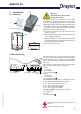
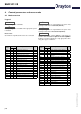

SHR 521 20
© Drayton 06334 SHR 521 20.monen.indd
| 8
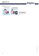
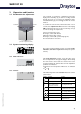
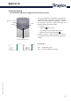
The system screen (active system scheme) shows the
schemes selected on the controller. It consists of several
system component symbols, which are - depending on the
current status of the system - either flashing, permanently
shown or hidden.
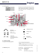
Sensors
Collector 1
Collector 2
Pumps
Heating
Sensor
Additional symbol for
operation of the burner
Valves
Store
Store heat exchanger
Store 2 or back-up heating
(with additional symbol)
Sensor store upper
Valves
Collectors
with collector sensor
Pump
3-way valves
The flow direction or the
current breaking capacity are
always shown.
Heating circuit
Store 1 and 2
with heat exchanger
Back-upheat
with burner symbol
Temperature sensor
2.2.3 System screen
only system screen
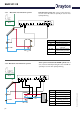
Constantly green: everything functioning correctly
Red/green flashing: initialisation phase
manual operation
Red flashing: sensor defect
(sensor symbol is flashing quickly)
2.3 Flashing symbols
2.3.2 LED flashing codes
2.3.1 System screen flashing symbols
• Pumps are flashing during starting phase
• Sensors are flashing if the respective sensor-mode is se-
lected.
• Sensors are flashing quickly in case of sensor defect.
• Burner symbol is flashing if back-up heat is activated.