Drayton SHR 521 20 49000720 *49000720* SHR 521 20 Installation Commissioning Operation Fault finding Examples B manual Thank you for buying a Drayton product. Please read this manual carefully to get the best perfomance from this unit.
SHR 521 20 Contents Disclaimer ............................................................................2 Safety Regulations ...............................................................2 Technical data and function ...............................................3 1. Installation .............................................................5 1.1 Mounting .................................................................................. 5 1.2 Electrical wiring ...........................................
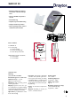
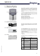
SHR 521 20 • Backlit multifunction display to monitor solar thermal systems • Up to 4 Pt1000 temperature sensors • Heat balancing • Stylish, easy-to-install housing • Simple 3-button operation • Solar operating hours counter and thermostat function ! Parts included: 1 x SHR 521 20 1 x accessory bag 1 x spare fuse T4A 2 x screws and wall plugs 4 x cable clamps and screws © Drayton 06334 SHR 521 20.monen.
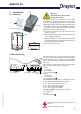
SHR 521 20 Examples SHR 521 20 Standard solar systems Solar systems with dual-mode DHW cylinder © Drayton 06334 SHR 521 20.monen.indd Please find detailed connection diagramms for these systems in chapter 1.
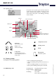
SHR 521 20 1. Installation display Warning! Switch-off mains supply before opening the housing. 1.1 Mounting cover pushbuttons cable conduits in the clamps can fuse 4A hanging The unit must only be located indoors. It is not suitable for installation in hazardous locations and should not be sited near to any electromagnetic field.The controller must additionally be equipped with an all-polar gap of at least 3 mm or with a gap according to the relevant installaton regulations, e.g.
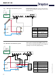
SHR 521 20 1.2.1 Allocation of terminals for system 1 Standard solar system with 1 store, 1 pump and 3 sensors. The sensor S4 / TRF can optionally be used for heat quantity balancing. Arr 1 S1 R1 Symbol S1 S2 S3 S3 S2 S4 / TRF S4 / TRF R1 Specification Collector sensor Store sensor lower Store sensor upper (optional) Sensor for heat quantity measurement (optional) Solar pump Solar system and dual-mode DHW cylinder with 1 store, 3 sensors and backup-heating.
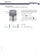
SHR 521 20 2. Operation and function 2.1 Pushbuttons for adjustment backwards forward 2 3 1 The controller is operated by 3 pushbuttons below the display. The forward-key (1) is used for scrolling forward through the menu or to increase the adjustment values. The backwards-key (2) is accordingly used for the reverse function. To confirm the current mode, hold down button 1 for 2 seconds. If an adjustment value is shown on the display, SEt is indicated.
SHR 521 20 2.2.3 System screen The system screen (active system scheme) shows the schemes selected on the controller. It consists of several system component symbols, which are - depending on the current status of the system - either flashing, permanently shown or hidden.
SHR 521 20 3. Commissioning To commission you have to adjust the solar thermal system Operation control lamp forward backwards 2 3 1. Ac power supply must be activated.The controller passes an initialisation phase in which the operating control lamp flashes red and green. When the initialisation is complete, the controller is in automatic operation with factory settings. The default system scheme is Arr 1. 2. - select Arr 1 - change into -mode (see 2.
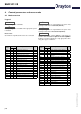
SHR 521 20 4. Control parameters and menu mode 4.1 Mode-overview Legend: x Corresponding mode is only available if the option heat quantity measurement is activated (OWMZ). Corresponding mode is available. x* Corresponding mode is available if the appropriate option is activated. MEDT Please note: S3 and S4 are only indicated if sensors are connected.
SHR 521 20 4.1.1 Indication of collector temperatures COL: Collector temperature display range: -40 ...+250 °C 4.1.2 Shows the current store temperature. • TST : store temperature (1-store-system) • TSTL : store temperature lower • TSTU : store temperature upper Indication of sensor 3 and sensor 4 S3, S4: Sensor temperatures display range: -40 ...+250 °C 4.1.4 • COL : collector temperature (1-collector-system) Indication of store temperatures TST,TSTL,TSTU: Store temperatures display range: -40 ..
SHR 521 20 4.1.6 Heat quantity balancing OHQM:Heat quantity balancing Adjustment range: OFF ...ON Factory setting: OFF FMAX: Volume flow in l/min Adjustment range 0 ... 20 in steps of 0,1 Factory setting 6,0 MEDT: Type of antifreeze Adjustment range 0 ...3 Factory setting 1 Heat quantity balancing is possible for all systems in conjunction with a flowmeter. You just have to activate the option heat quantity balancing in the mode OHQM.
SHR 521 20 4.1.7 ∆T-adjustment DT O: Switch-on temperature Adjustment range 1,0...20,0 K Factory setting 6.0 Basically the controller works in the same way as a standard differential controller. If the switch-on difference (DT O) is reached, the pump is activated. If the selected switch-off temperature is underrun (DT F), the controller switches off. DT F: Switch-off temperature diff. Adjustment range 0,5 ... 19,5 K Factory setting 4.
SHR 521 20 4.1.9 Collector temperature limit Collector emergency shutdown EM: Collector temperature limit Adjustment range 110 ... 200 °C, Factory setting 140 °C 4.1.10 System cooling OCX: Option system cooling Adjustment OFF ... ON Factory setting OFF CMX: Maximum collector temp. Adjustment range 100 ...190 °C Factory setting120 °C If the selected collector limit temperature (EM) is exceeded, the solar pump (R1/R2) is deactivated to avoid overheating of the solar components (collector emergency shutdown).
SHR 521 20 4.1.13 Recooling function If the selected maximum store temperature (S MX) is reached, the solar pump remains activated to avoid overheating the collector. The store temperature might continue to increase but only up to 95 °C (emergency shutdown of the store). In the evening the solar system continues running until the store is cooled down to the selected maximum store temperature via collector and pipes. OREC: option recooling adjustment range OFF ...ON Factory setting: OFF 4.1.
SHR 521 20 4.1.16 Operating mode HAND / HND1 / HND2: Operating mode Adjustment range: OFF, AUTO, ON Factory setting: AUTO For commissioning and service work the operating mode of the controller can be manually selected by selecting the adjustment value HAND / HND1 / HND2, in which the following adjustments can be made: • HAND / HND1 / HND2 Operating mode OFF : relay off (flashing) + AUTO : relay in automatic operation ON : relay on (flashing) + 4.1.
SHR 521 20 5.Tips for fault finding can fuse T4A T4A If a malfunction occurs, a notification is given on the display of the controller: 220 ... 240 V~ R1 2 (1) A (220 ... 240) V~ R2 2 (1) A (220 ... 240) V~ Temp. Sensor Pt1000 S1 1 2 3 S2 4 S3 5 6 S4 7 8 12 13 14 Warning symbol N R2 N R1 N L 15 16 17 18 19 20 Operating control lamp Operating control lamp flashes red. On the display the symbol and the symbol appear. Sensor defect.
SHR 521 20 5.1Various: Pump is overheated, there is no heat transfer from collector to the store, feed flow and return flow are equally warm, perhaps also bubble in the lines. Pump starts for a short moment, switches off, switches on again, etc.
SHR 521 20 a b Stores are cooled during the night. Control the return flow preventer in warm water circulation- o.k. Does collector circuit pump run during the night? no yes Collector temperature is at night higher than ambient temperature. no yes yes Check the controller functions correctly no Is store insulation close enough to the store? yes no no Warm water outflow upwards? no yes Increase the insulation.
SHR 521 20 6. Accessories Sensors Our product range includes high-precision platinum temperature sensors, flatscrew sensors, ambient temperature sensors, indoor temperature sensors, cylindrical clip-on sensors and irradiation sensors, which can be used as full sensors with sensor pocket. Overvoltage protection We highly recommend installing overvoltage protection in order to avoid overvoltage damage to the collector (e.g. by lightning).