Vigor2130 Series High Speed Gigabit Router User’s Guide Version: 2. 1 Firmware Version: V1.5.
Copyright Information Copyright Declarations Copyright 2012 All rights reserved. This publication contains information that is protected by copyright. No part may be reproduced, transmitted, transcribed, stored in a retrieval system, or translated into any language without written permission from the copyright holders. Trademarks The following trademarks are used in this document: z Microsoft is a registered trademark of Microsoft Corp.
European Community Declarations Manufacturer: Address: Product: DrayTek Corp. No. 26, Fu Shing Road, HuKou County, HsinChu Industrial Park, Hsin-Chu, Taiwan 303 Vigor2130 Series Router DrayTek Corp. declares that Vigor2130 Series of routers are in compliance with the following essential requirements and other relevant provisions of R&TTE Directive 1999/5/EEC.
Table of Contents Preface .........................................................................................................1 1.1 Features .................................................................................................................................. 1 1.2 Web Configuration Buttons Explanation ................................................................................. 1 1.3 LED Indicators and Connectors ........................................................................
3.6 How to configure Dynamic DNS Service on Vigor2130........................................................ 64 Web Configuration ....................................................................................67 4.1 WAN ...................................................................................................................................... 67 4.1.1 Internet Access ............................................................................................................... 69 4.1.
4.8.1 Remote Access Control ................................................................................................ 169 4.8.2 PPTP Remote Dial-in.................................................................................................... 170 4.8.3 IPSec Remote Dial-in ................................................................................................... 173 4.8.4 Remote Dial-in Status...............................................................................................
4.16 Diagnostics........................................................................................................................ 265 4.16.1 Ping............................................................................................................................. 265 4.16.2 Trace Route ................................................................................................................ 266 4.16.3 Routing Table .........................................................................
Preface The Vigor2130 series are the routers with high speed in data transmission through WAN port and LAN ports. With hardware NAT acceleration, the rate of Vigor2130 series can be ideal for multi-media application. With the development of NGN (Next Generation Network), you may recently hear the news about FTTx deployment in your local area or even have already subscribed the unbundling last mile service (e.g. VDSL2) from local ITSP for FTTx.
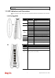
Note: For the other buttons shown on the web pages, please refer to Chapter 4 for detailed explanation. 1.3 LED Indicators and Connectors Before you use the Vigor router, please get acquainted with the LED indicators and connectors first. 1.3.1 For Vigor2130 LED Status Explanation ACT Blinking Off On Off On (Orange) On (Green) Off Blinking On (Orange) On (Green) Off Blinking On Blinking On On The router is powered on and running normally. The router is powered off. Hardware NAT is enabled.
Interface Description Factory Reset Restore the default settings. Usage: Turn on the router (ACT LED is blinking). Press the hole and keep for more than 5 seconds. When you see the ACT LED begins to blink rapidly than usual, release the button. Then the router will restart with the factory default configuration. Connector for a power adapter. Power Switch.
1.3.2 For Vigor2130n LED Status Explanation ACT (Activity) Blinking The router is powered on and running normally. The router is powered off. Hardware NAT is enabled. Hardware NAT is disabled. The port is connected with 100Mbps. The port is connected with 1000Mbps. The port is disconnected. It will blink while transmitting data. The port is connected with 100Mbps. The port is connected with 1000Mbps. The port is disconnected. The data is transmitting. A USB device is connected and active.
Interface Description Factory Reset Restore the default settings. Usage: Turn on the router (ACT LED is blinking). Press the hole and keep for more than 5 seconds. When you see the ACT LED begins to blink rapidly than usual, release the button. Then the router will restart with the factory default configuration. Connector for a power adapter. Power Switch.
1.3.3 For Vigor2130Vn LED Status Explanation ACT Blinking The router is powered on and running normally. The router is powered off. Hardware NAT is enabled. Hardware NAT is disabled. The port is connected with 100Mbps. The port is connected with 1000Mbps. The port is disconnected. It will blink while transmitting data. The port is connected with 100Mbps. The port is connected with 1000Mbps. The port is disconnected. The data is transmitting. A USB device is connected and active.
Interface Description Phone2/Phone1 Factory Reset Connector of analog phone for VoIP communication. Restore the default settings. Usage: Turn on the router (ACT LED is blinking). Press the hole and keep for more than 5 seconds. When you see the ACT LED begins to blink rapidly than usual, release the button. Then the router will restart with the factory default configuration. Connector for a power adapter. Power Switch.
1.4 Hardware Installation Before starting to configure the router, you have to connect your devices correctly. 1. Connect this device to a modem with a RJ-45 cable. 2. Connect one port of 4-port switch to your computer with a RJ-45 cable. This device allows you to connect 4 PCs directly. 3. Connect Phone port to a conventional analog telephone. 4. Connect detachable antennas to the router for Vigor2130 series (n model). 5. Connect one end of the power cord to the power port of this device.
Stand Installation The Vigor2130 must be placed erectly. Therefore you have to install a stand onto the router to make it standing firmly. Please follow the figures listed below to finish the installation.
1.5 Printer Installation You can install a printer onto the router for sharing printing. All the PCs connected this router can print documents via the router. The example provided here is made based on Windows XP/2000. For Windows 98/SE/Vista, please visit www.draytek.com. Before using it, please follow the steps below to configure settings for connected computers (or wireless clients). 1. Connect the printer with the router through USB/parallel port. 2. Open Start->Settings-> Printer and Faxes. 3.
4. Click Local printer attached to this computer and click Next. 5. In this dialog, choose Create a new port Type of port and use the drop down list to select Standard TCP/IP Port. Click Next.
6. In the following dialog, type 192.168.1.1 (router’s LAN IP) in the field of Printer Name or IP Address and type IP_192.168.1.1 as the port name. Then, click Next. 7. Click Standard and choose Generic Network Card. 8. Then, in the following dialog, click Finish.
9. Now, your system will ask you to choose right name of the printer that you installed onto the router. Such step can make correct driver loaded onto your PC. When you finish the selection, click Next. 10. For the final stage, you need to go back to Control Panel-> Printers and edit the property of the new printer you have added. 11. Select "LPR" on Protocol, type p1 (number 1) as Queue Name. Then click OK. Next please refer to the red rectangle for choosing the correct protocol and UPR name.
The printer can be used for printing now. Most of the printers with different manufacturers are compatible with vigor router. Note 1: Some printers with the fax/scanning or other additional functions are not supported. If you do not know whether your printer is supported or not, please visit www.draytek.com to find out the printer list. Open Support >FAQ; find out the link of Printer Server and click it; then click the What types of printers are compatible with Vigor router? link.
Basic Settings For using the router properly, it is necessary for you to change the password of web configuration for security and adjust primary basic settings. This chapter explains how to setup a password for accessing into the web configurator of Vigor router and how to adjust settings for accessing Internet successfully. 2.1 Accessing Web Page 1. Make sure your PC connects to the router correctly.
2.2 Changing Password Please change the password for the original security of the router. 1. Open a web browser on your PC and type http://192.168.1.1. A pop-up window will open to ask for username and password. 2. Please type “admin/admin” as Username/Password for accessing into the web configurator with admin mode. 3. Now, the Main Screen will appear. Note: The home page will change slightly in accordance with the type of the router you have. 4.
6. Now, the password has been changed. Next time, use the new password to access the Web Configurator for this router. 2.3 Quick Start Wizard Notice: Quick Start Wizard for user mode operation is the same as for admin mode operation. If your router can be under an environment with high speed NAT, the configuration provide here can help you to deploy and use the router quickly. The first screen of Quick Start Wizard is welcome page, please click Next.
2.3.1 Setting up the Password The first screen of Quick Start Wizard is entering login password. After typing the password, please click Next. 2.3.2 Setting up the Time Zone On the next page as shown below, please select the Time Zone for the router installed and specify the NTP server(s). Then click Next for next step.
2.3.3 Setting up the Internet Connection On the next page as shown below, please select the appropriate connection type according to the information from your ISP. There are five types offered in this page. Each connection type will bring out different web page. Static IP You will receive a fixed public IP address or a public subnet, namely multiple public IP addresses from your DSL or Cable ISP service providers.
Item Description IP Address Type the IP address. Subnet Mask Type the subnet mask. Gateway Type the gateway IP address. Primary DNS Server Type in the primary IP address for the router. Secondary DNS Server Type in secondary IP address for necessity in the future. Enable The router will detect the MAC address automatically. Or, check the box to enable MAC address cloning. Clone MAC Address It is available when the box of Enable is checked. Click Clone PC Address.
Item Description After finishing the settings here, please click Next. PPPoE PPPoE stands for Point-to-Point Protocol over Ethernet. It relies on two widely accepted standards: PPP and Ethernet. It connects users through an Ethernet to the Internet with a common broadband medium, such as a single DSL line, wireless device or cable modem. All the users over the Ethernet can share a common connection. PPPoE is used for most of DSL modem users.
Item Description MTU Size It means Max Transmit Unit for packet. The default setting will be specified by the system automatically. Therefore, keep this field in blank. Enable The router will detect the MAC address automatically. Or, check the box to enable MAC address cloning. Clone MAC Address It is available when the box of Enable is checked. Click Clone PC Address. The result will be displayed in the field of MAC Address. After finishing the settings here, please click Next.
Item Description Subnet Mask Type the subnet mask if you chose Static IP as the WAN IP. Redial Policy If you want to connect to Internet all the time, you can choose Always On. Otherwise, choose Connect on Demand. Idle Time Out Set the timeout for breaking down the Internet after passing through the time without any action. MTU Size It means Max Transmit Unit for packet. The default setting will be specified by the system automatically. Therefore, keep this field in blank.
Item Description SSID It means the identification of the wireless LAN. SSID can be any text numbers or various special characters. The default SSID is "DrayTek". We suggest you to change it. Encryption Select an appropriate encryption mode to improve the security and privacy of your wireless data packets. Each encryption mode will bring out different web page and ask you to offer additional configuration.
WPA-PSK If you choose WPA-PSK as the security configuration, you have to specify WPA mode, algorithm and pre-shared key. Available settings are explained as follows: Item Description Type The WPA encrypts each frame transmitted from the radio using the key, which either PSK (Pre-Shared Key) entered manually in this field below or automatically negotiated via 802.1x authentication. Select WPA, WPA2 or Auto as WPA mode. WPA Algorithm Choose the WPA algorithm, TKIP, AES or Auto.
If you choose WPA-Radius as the security configuration, you have to specify WPA mode, algorithm, Radius server, Radius server port and Radius server secret respectively. Available settings are explained as follows: Item Description Type The WPA encrypts each frame transmitted from the radio using the key, which either PSK (Pre-Shared Key) entered manually in this field below or automatically negotiated via 802.1x authentication. Select WPA, WPA2 or Auto as WPA mode.
WPS WPS (Wi-Fi Protected Setup) provides easy procedure to make network connection between wireless station and wireless access point (vigor router) with the encryption of WPA and WPA2. If you choose WPS as the security configuration, you can press Start WPS PIN and Start WPS PBC to complete the wireless connection. Available settings are explained as follows: Item Description Configure via Push Button Click Start PBC to invoke Push-Button style WPS setup procedure.
2.3.5 Saving the Wizard Configuration Now you can see the following screen. It indicates that the setup is complete. Different types of connection modes will have different summary. Click Finish and then restart the router. 2.4 Online Status The online status shows the system status, WAN status, and other status related to this router within one page. If you select PPPoE as the protocol, you will find out a link of Dial PPPoE or Drop PPPoE in the Online Status web page.
Item Description LAN interface. RX Packets-Displays the total received packets at the LAN interface. TX Bytes-Displays the total transmitted bytes at the LAN interface. RX Bytes-Displays the total received packets at the LAN interface. IPv6 Address-Displays the IPv6 address of the LAN interface. WAN Status IP-Displays the IP address of the WAN interface. GW IP-Displays the IP address of the default gateway. Mode-Displays the type of WAN connection (e.g., PPPoE).
2.6 Registering Vigor Router You have finished the configuration of Quick Start Wizard and you can surf the Internet at any time. Now it is the time to register your Vigor router to MyVigor website for getting more service. Please follow the steps below to finish the router registration. 1 Please login the web configuration interface of Vigor router by typing “admin/admin” as User Name / Password. 2 Click Support Area>>Production Registration from the home page.
4 The following page will be displayed after you logging in MyVigor. From this page, please click Add or Product Registration. 5 When the following page appears, please type in Nickname (for the router) and choose the right registration date from the popup calendar (it appears when you click on the box of Registration Date). After adding the basic information for the router, please click Submit. 6 When the following page appears, your router information has been added to the database.
7 Now, you have finished the product registration. 8 After clicking OK, you will see the following page. Your router has been registered to myvigor website successfully. If you have not activated web content filter service by using Service Activation Wizard, you can activate the service from this step. Please click the serial number link. 9 From the Device’s Service section, click the Trial.
10 In the following page, check the box of “I have read and accept the above Agreement”. The system will find out the date for you to activate this version of service. Then, click Next. 11 When this page appears, click Register. 12 Wait for a moment until the following page appears. 13 Click Close.
This page is left blank.
Tutorials and Applications 3.1 How to Configure Multi-VLAN in Vigor Router Vigor2130 supports the function of Multi-VLAN (firmware version: 1.4.0 and after). It can specify a VLAN ID for WAN port and offers more advanced environmental application for the users through the bridge technique in WAN port and LAN port. I. Way to Configure To enable such function, please do the following: 1. Open WAN>>802.1Q VLAN Tag Configuration. Check the box of Enable Multi-VLAN Setup. 2.
II. Example Chart of Structure z PC 1 connects to the first LAN port of Vigor2130 and accesses Internet with WAN VLAN. z PC 2 connects to the forth LAN port of Vigor2130 and accesses Internet with LAN VLAN. z FXS 1 Phone connects to the FXS 1 port of Vigor2130, registers, sends and receives phone call with VoIP WAN. Functions Configuration 1. Open WAN>>Internet. Set PPPoE as the Connection Type and fill in the Username and Password offered by your ISP.
2. Open WAN>>802.1Q VLAN Tag Configuration to configure Multi-VLAN. Refer to the following graphic. 3. Open WAN>>VoIP WAN to configure VoIP WAN Setting. Note: At present, only DHCP, PPPoE and Static connection types are available.
4. Open VoIP >>SIP Accounts. Specify the connection interface for VoIP in the field of Register via. 5. Connect your PC or network device to the forth LAN port and type the username and password for PPPoE connection mode.
3.2 LAN to LAN IPSec VPN between Vigor2130 and Vigor2820 using Main mode In this document we will introduce how to create a LAN to LAN IPSec VPN between Vigor2130 and a Vigor2820 using Main mode. We use the following scenario. Case 1: VPN direction from Vigor2130 to Vigor2820 VPN configuration on Vigor2130 1. Create a LAN-to-LAN profile. 2. Enable it and give it a name. In this example the profile name is “Demo”. 3. Enter Vigor2820’s WAN IP address in the Remote IP field. 4.
6. Enter Vigor2130’s private network in the Local Network / Mask field. Enter Vigor2820’s private network in the Remote Network / Mask field. 7. Use default value “Automatic” for IKE phase 1 and phase 2 proposals. 8. Click OK. 9. Accessing the VPN network of Vigor2820 from a PC behind Vigor2130 to initiate the VPN connection, for example, ping 192.168.1.x from a PC (192.168.30.x). Vigor2130 will be triggered to dial the IPSec VPN to Vigor2820. After the VPN is connected, you can monitor the status.
VPN configuration on Vigor2820 1. Create a LAN-to-LAN profile. 2. Enable it and give it a name. In this example the profile name is “test”. 3. Select Dial-in as Call Direction. 4. In Dial-Out Settings part, select IPSec Tunnel and press the Advanced button. 5. In Dial-In Settings part, please enable Specify Remote VPN Gateway and enter WAN IP address of Vigor2130 in the Peer VPN Server ID field.
6. Setup a pre-shared key, which must be the same as in Vigor2130. 7. Enter Vigor2130’s private network in the Remote Network IP / Mask field. 8. Click OK. Note: Vigor2130 supports the following proposals by default.
Case 2: VPN direction from Vigor2820 to Vigor2130 VPN configuration on Vigor2130 1. Create a LAN-to-LAN profile. 2. Enable it and give it a name. In this example the profile name is “Demo”. 3. Enter WAN IP address of Vigor2820 in the Remote IP field. 4. Select Main Mode as IKE phase 1 mode. 5. Setup a pre-shared key, which must be the same as in Vigor2820. 6. Enter Vigor2130’s private network in the Local Network / Mask field. 7.
VPN configuration on Vigor2820 1. Create a LAN-to-LAN profile. 2. Enable it and give it a name. In this example the profile name is “test”.
3. Select Dial-Out as Call Direction and enable Always on. 4. Select IPSec Tunnel and enter Vigor2130’s WAN IP address in the Server IP/Host Name for VPN field. 5. Setup a pre-shared key, which must be the same as in Vigor2130. 6. Select ESP (High) and 3DES with Authentication. 7. Enter Vigor2130’s private network in the Remote Network IP / Mask field. 8. Click OK.
3.3 LAN to LAN IPSec VPN between Vigor2130 and Vigor2820 using Agressive mode In this document we will introduce how to create a LAN to LAN IPSec VPN between Vigor2130 and a Vigor2820 using Aggressive mode. We use the following scenario. Case 1: VPN direction from Vigor2130 to Vigor2820 VPN configuration on Vigor2130 1. Create a LAN-to-LAN profile. 2. Enable it and give it a name. In this example the profile name is “Demo”. 3. Enter Vigor2820’s WAN IP address in the Remote IP field. 4.
5. Setup a pre-shared key, which must be the same as in Vigor2820. 6. Setup the Local Identity and Remote Identity, which are for Vigor2130 and Vigor2820 respectively. During IPSec Aggressive mode negotiation, the VPN client must send its identity to the VPN server for verification. The VPN client may also verify the identity of the VPN server, which is optional. In this example we setup ‘vigor2130’ as the identity of Vigor2130, and ‘vigor2820’ as the identity of Vigor2820. 7.
VPN configuration on Vigor2820 1. Create a LAN-to-LAN profile. 2. Enable it and give it a name. In this example the profile name is “test”.
3. Select Dial-in as Call Direction. 4. In Dial-Out Settings part, select IPSec Tunnel and press the Advanced button. 5. In the pop-up window please enter vigor2820 in the Local ID field. Click OK to return to the profile setting page. 6. In Dial-In Settings part, please enable Specify Remote VPN Gateway and enter vigor2130 in the Peer ID field. 7. Setup a pre-shared key, which must be the same as in Vigor2130. 8. Enter Vigor2130’s private network in the Remote Network IP / Mask field. 9.
Case 2: VPN direction from Vigor2820 to Vigor2130 VPN configuration on Vigor2130 1. Create a LAN-to-LAN profile. 2. Enable it and give it a name. In this example the profile name is “Demo”. 3. Enter 0.0.0.0 in the Remote IP field. 4. Select Aggressive Mode as IKE phase 1 mode. 5. Setup a pre-shared key, which must be the same as in Vigor2820. 6. Setup the Local Identity and Remote Identity, which are for Vigor2130 and Vigor2820 respectively.
VPN configuration on Vigor2820 1. Create a LAN-to-LAN profile.
2. Enable it and give it a name. In this example the profile name is “test”. 3. Select Dial-Out as Call Direction and enable Always on. 4. Select IPSec Tunnel and enter Vigor2130’s WAN IP address in the Server IP/Host Name for VPN field. 5. Setup a pre-shared key, which must be the same as in Vigor2130. 6. Select ESP (High) and 3DES with Authentication. 7. Press the Advanced button. 8.
3.4 How to configure settings for DLNA Service in Vigor2130 Introduction DLNA (Digital Living Network Alliance) is a framework which personal computer, HDD video recorder, television and other digital devices can share each other data through network connection. The DLNA devices are divided into two functions. One is server side which transmits images, music and video, and the other is client side which receives data only. Some devices support both functions.
2. Make sure Internet connection is done. Open USB Application>>DLNA Server and click Install to install DLNA service into the USB storage device. 3. During the process of installation, you can click Show Detail to view the installation procedure. 4. After finished the service installation, the configuration page will be open automatically. Please click Enable and type a name in the field of Server Name. Then, click OK to activate DLNA service.
5. After enabled successfully, new media device can be seen in My Network Places. The name of the media device is the Server Name configured in Step 4. Note: If you cannot see the media device in Network view, please check and make sure the UPnP service has been enabled Control Panel>>Administrative Tools >>Services.
6. For the users of Windows7, please use Windows Media Player (WMP) to browse and play the files stored in the new service device. For other systems, please use VLC media player (downloaded from Internet) to browse/locate and play the files. Notes z Before removing USB storage device, please DISABLE DLNA service and then remove the device. z The audio and video files might not be played normally due to unrecognized equipment set in client.
3.5 How to download BT Torrent to USB Device via Vigor Router Download BT Torrent 1. Plug USB storage disk into the USB slot of Vigor2130. Access into the web configuration interface of Vigor2130. 2. Open USB Application>>Disk Status. 3. Wait for few seconds for the router to detect it. If the disk is detected, it will be shown as the following figure. 4. Make sure that WAN connection has been established. 5. Open USB Application >> Bit Torrent Download.
6. Simply wait for a few minutes to finish the installation. 7. When the installation is finished, the following page will be displayed. 8. Click the link of Open Web Client to open another window.
9. Click Open. A pop up dialog will appear. 10. Click Select File to open the following dialog. Choose the seed of BT torrent file and click Open. Note: Before uploading torrent files to the router, please search from Internet and store the seed of the BT torrent on our hard disk first.
11. Next, the router will start to download the file to the USB disk. You can add new seed of torrent file one by one by clicking Open to let the router download them at one time. Share the file after downloading completed 1. Access into Vigor2130 web configuration interface and open USB Application >> USB General Settings. Enable the Disk Sharing function by checking the box and click OK. 2. Open USB Application >> Disk Shares. Click Add a New Entry.
3. In the following screen, add a new entry for the sharing folder/name. In this case, we give a name of bt_folder as Share Name for home folder (“/”) . Click OK. 4. Now, PCs in LAN connected to Vigor2130 can open a browser from his / her computer. Simply type “\\192.168.1.1” in the field of Address and then click Go.
5. The sharing disk with the name of “bt_folder” created above will be shown as the following figure. 6. Double click bt_folder to view the files in the disk.
7. If you want to check the BT Torrent files downloaded from Internet to USB disk, access into bt_folder>>downloads. (Note: While the file is downloading, the file extension name will be “part”.
3.6 How to configure Dynamic DNS Service on Vigor2130 DDNS stands for Dynamic DNS. Simply put, using this service gives a name to your IP. If you are hosting something on your line, people wouldn't have to bother typing your IP. They can just type in your domain name. It also helps when your ISP only provides dynamic IP address. Users won't need to discover what your new IP is, they can simply type your domain name. Vigor2130 supports dyndns.org, no-ip.org, chang-ip.com, zoneedit.com, and freedns.afraid.
3. Copy the character strings from the right of the ? in the address bar. 4. Login to Vigor2130 by WUI, and go to Application >>Dynamic DNS page. Select freedns.afraid.org, and fill in the username as you applied for the service. 5. Past the strings what you copied on step3 on password field. 6. Click OK to save the configuration. Now, you can check the service by using nslookup command on your computer or check the syslog information on Vigor2130.
This page is left blank.
Web Configuration This chapter will guide users to execute advanced (full) configuration through admin mode operation. 1. Open a web browser on your PC and type http://192.168.1.1. The window will ask for typing username and password. 2. Please type “admin/admin” on Username/Password for administration operation. Now, the Main Screen will appear. Be aware that “Admin mode” will be displayed on the bottom left side. 4.
From 10.0.0.0 to 10.255.255.255 From 172.16.0.0 to 172.31.255.255 From 192.168.0.0 to 192.168.255.255 What are Public IP Address and Private IP Address As the router plays a role to manage and further protect its LAN, it interconnects groups of host PCs. Each of them has a private IP address assigned by the built-in DHCP server of the Vigor router. The router itself will also use the default private IP address: 192.168.1.1 to communicate with the local hosts.
Below shows the menu items for WAN. 4.1.1 Internet Access This page allows you to set WAN configuration with different modes. Use the Connection Type drop down list to choose one of the WAN modes. The corresponding page will be displayed. Available settings are explained as follows: Item Description WAN IP Configuration Enable - Check the box to enable the WAN IP configuration. Connection Type- Use the Connection Type drop down list to choose one of the WAN modes.
be applied to each connection type. Below shows the configuration page for each connection type: Static For static IP mode, you usually receive a fixed public IP address or a public subnet, namely multiple public IP addresses from your DSL or Cable ISP service providers. In most cases, a Cable service provider will offer a fixed public IP, while a DSL service provider will offer a public subnet. If you have a public subnet, you could assign an IP address or many IP address to the WAN interface.
Available settings are explained as follows: Item Description Static IP Settings IP Address -Type the IP address. Subnet Mask -Type the subnet mask. Gateway IP Address -Type the gateway IP address. Primary DNS Server -You must specify a DNS server IP address here because your ISP should provide you with usually more than one DNS Server. If your ISP does not provide it, the router will automatically apply default DNS Server IP address: 198.95.1.1 to this field.
Clone MAC Address Enable – Enable the feature. It is available when the box of Enable is checked. Click Clone MAC Address. The result will be displayed in the field of MAC Address. Mail/SMS Alert Alert Types – Specify the type of the alert (mail, SMS, or Mail and SMS) that Vigor system will use to send a message to the user. Event types – Specify the event when the system must send a notification to the user by mail and/or SMS. After finishing all the settings here, please click OK to activate them.
Available settings are explained as follows: Item Description DHCP Settings Router Name -Type in a name for the router. It must be the same as the name used in Syslog. Domain Name -Type the domain name (e.g., draytek) to fit the request of some ISPs. MTU Size -It means Max Transmit Unit for packet. The default setting will be specified by the system automatically. Therefore, keep this field in blank.
PPPoE To choose PPPoE as the accessing protocol of the internet, please select PPPoE from the Internet Access menu. The following web page will be shown. Available settings are explained as follows: Item Description PPPoE Settings Username -Type in the username provided by ISP in this field. Password -Type in the password provided by ISP in this field. Redial Policy-If you want to connect to Internet all the time, you can choose Always On. Otherwise, choose Connect on Demand.
Fixed IP (IPCP) - Usually ISP dynamically assigns IP address to you each time you connect to it and request. In some case, your ISP provides service to always assign you the same IP address whenever you request. In this case, you can fill in this IP address in the Fixed IP field. Please contact your ISP before you want to use this function. Click Yes to use this function Fixed IP Address (IPCP) -Type in a fixed IP address in the box if you click Yes for Fixed IP(IPCP).
PPTP/L2TP To use PPTP/L2TP as the accessing protocol of the internet, please choose PPTP/L2TP from Connection Type drop down menu. The following web page will be shown. Available settings are explained as follows: Item Description PPTP Settings /L2TP Settings Username -Type in the username provided by ISP in this field. Password -Type in the password provided by ISP in this field. Server Address-Type in the IP address for PPTP /L2TP server.
address here because your ISP should provide you with usually more than one DNS Server. If your ISP does not provide it, the router will automatically apply default DNS Server IP address: 194.109.6.66 to this field. Secondary DNS Server-You can specify secondary DNS server IP address here because your ISP often provides you more than one DNS Server. If your ISP does not provide it, the router will automatically apply default secondary DNS Server IP address: 194.98.0.1 to this field.
Event types – Specify the event when the system must send a notification to the user by mail and/or SMS. After finishing all the settings here, please click OK to activate them.
3G USB Modem If your router connects to a 3G modem and you want to access Internet via 3G modem, choose 3G as connection type and type the required information in this web page. Available settings are explained as follows: Item Description 3G USB Modem Settings SIM PIN code -Type PIN code of the SIM card that will be used to access Internet. Modem Initial String1/2-Such value is used to initialize USB modem. Please use the default value. If you have any question, please contact to your ISP.
WAN Connection Detection Mode -Such function allows you to verify whether network connection is alive or not through ARP Detect or Ping Detect. Choose ARP Detect or Ping Detect for the system to execute for WAN detection. Ping IP-If you choose Ping Detect as detection mode, you have to type IP address in this field for pinging. Clone MAC Address Enable – Enable the feature. It is available when the box of Enable is checked. Click Clone MAC Address.
56K Modem If your router connects to a 56K modem and you want to access Internet via 56K modem, choose 56K Modem as connection type and type the required information in this web page. Available settings are explained as follows: Item Description 56K Modem Settings Phone Number-Type the phone number offered by the ISP for dial-out connection. PPP Username-Type the PPP username (optional). PPP Password-Type the PPP password (optional).
Mail/SMS Alert Alert Types – Specify the type of the alert (mail, SMS, or Mail and SMS) that Vigor system will use to send a message to the user. Event types – Specify the event when the system must send a notification to the user by mail and/or SMS. After finishing all the settings here, please click OK to activate them. 4G USB Modem If your router connects to a 4G USB modem and you want to access Internet via it, choose 4G USB Modem as connection type and type the required information.
APN Name - APN means Access Point Name which is provided and required by some ISPs. WAN Connection Detection Mode -Such function allows you to verify whether network connection is alive or not through ARP Detect or Ping Detect. Choose ARP Detect or Ping Detect for the system to execute for WAN detection. Ping IP-If you choose Ping Detect as detection mode, you have to type IP address in this field for pinging. Clone MAC Address Enable – Enable the feature.
4.1.2 Multi-VLAN Vigor2130 series offers multi-VLAN function to make the data transmission with security. Data transmitting through the Ethernet port for connecting to Internet can be tagged with an ID number specified here for ensuring the security. In addition, each LAN port also can be tagged with an ID number in local network to reach the goal of protection. If all the boxes are checked, it means that Internet connection and data transmission can be done via 4 VLAN groups.
port will be tagged with VLAN ID number specified here. The range of ID number you can type is from 2 - 4096. VoIP WAN Setting – Click this link to open VoIP WAN setting. IPTV WAN VLAN Setting Vigor router supports IPTV application (traditional television channel, movie or VoD service) through the second WAN IP under PPPoE connection mode. Enable IPTV WAN Setup - Check the box to enable IPTV WAN configuration.
VoIP/ IPTV / Management WAN Setting VoIP/ IPTV / Management WAN is the interface specified for the usage of VoIP/ IPTV / Management. Based on the connection type selected, you need to specify different settings. When Static IP is selected as connection type, you need to configure the following settings: Available settings are explained as follows: Item Description Static IP Settings IP Address - Type the IP address obtained from ISP for the usage of VoIP.
Available settings are explained as follows: Item Description DHCP Setting Router Name- Type the name of the router. Domain Name - Type the domain name obtained from the ISP. Mail/SMS Alert Alert Types – Specify the type of the alert (mail, SMS, or Mail and SMS) that Vigor system will use to send a message to the user. Event types – Specify the event when the system must send a notification to the user by mail and/or SMS.
Available settings are explained as follows: Item Description PPPoE Setting Username - Type the name obtained from the ISP. Password - Type the password obtained from the ISP. Confirm Password -Type the password again for confirmation. MTU Size - It means Max Transmit Unit for packet. The default setting will be specified by the system automatically. Therefore, keep this field in blank.
Flow Control If flow control is enabled by checking Configured box, both parties can send PAUSE frame to the transmitting device(s) if the receiving port is too busy to handle. If not, there will be no flow control in the port. It drops the packet if too much to handle. Current Rx: indicates whether pause frames on the port are obeyed. Current Tx: indicates whether pause frames on the port are transmitted.
After finishing all the settings here, please click OK to activate them. 4.1.4 Backup This page is used to setup 3G/56K backup function. If you enable 3G/56K backup, make sure your WAN connection type is not in 3G/56K mode. When the WAN connection is broken, router will try to keep the connection with 3G/56K mode. After WAN connection is recovered, router will disconnect the 3G/56K connection automatically.
question, please contact to your ISP. PPP Username - Type the PPP username (optional). PPP Password -Type the PPP password (optional). WAN Connection Detection Mode -Such function allows you to verify whether network connection is alive or not through ARP Detect or Ping Detect. Choose ARP Detect or Ping Detect for the system to execute for WAN detection. Ping IP-If you choose Ping Detect as detection mode, you have to type IP address in this field for pinging.
Item 56K Backup Description Enable 56K Backup -Check this box to enable such function. Phone Number - Type the phone number offered by the ISP for dial-out connection. PPP Username -Type the PPP username (optional). PPP Password - Type the PPP password (optional). WAN Connection Detection Mode -Such function allows you to verify whether network connection is alive or not through ARP Detect or Ping Detect. Choose ARP Detect or Ping Detect for the system to execute for WAN detection.
4.2 LAN Local Area Network (LAN) is a group of subnets regulated and ruled by router. The design of network structure is related to what type of public IP addresses coming from your ISP. Basics of LAN The most generic function of Vigor router is NAT. It creates a private subnet of your own. As mentioned previously, the router will talk to other public hosts on the Internet by using public IP address and talking to local hosts by using its private IP address.
What is Routing Information Protocol (RIP) Vigor router will exchange routing information with neighboring routers using the RIP to accomplish IP routing. This allows users to change the information of the router such as IP address and the routers will automatically inform for each other. What is Static Route When you have several subnets in your LAN, sometimes a more effective and quicker way for connection is the Static routes function rather than other method.
4.2.1 General Setup This page provides you the general settings for LAN. Click LAN to open the LAN settings page and choose General Setup. Available settings are explained as follows: Item LAN IP Network Configuration Description IP Address - Type in private IP address for connecting to a local private network (Default: 192.168.1.1). Subnet Mask - Type in an address code that determines the size of the network. (Default: 255.255.255.0/ 24) For IP Routing Usage - Click Enable to invoke this function.
related IP settings to any local user configured as a DHCP client. It is highly recommended that you leave the router enabled as a DHCP server if you do not have a DHCP server for your network. You can configure the router to serve as a DHCP server for the 2nd subnet. Check the box to enable DHCP server setting. Enable Relay Agent – Check it to enable such function. It allows you to specify which subnet that DHCP server is located the relay agent should redirect the DHCP request to.
4.2.2 Ports Ports page is used to change the setting for LAN ports. You can set or reset the following items. All of them are described in detail below. Available settings are explained as follows: Item Description Port It displays current network interface. Link It displays current connection status. Green light means the WAN connection is successful. Speed Current - It displays current speed that the router uses.
Discard - It determines whether the MAC drops frames after an excessive collision has occurred. If yes, a frame is dropped after excessive collision. This is IEEE Standard 802.3 half-duplex flow control operation. Restart - It determines whether the MAC retransmits frames after an excessive collision has occurred. If set, a frame is not dropped after excessive collisions, but the backoff sequence is restarted. This is a violation of IEEE Standard 802.
4.2.3 MAC Address Table This page allows you to set timeouts for entries in dynamic MAC Table and configure the static MAC table here. Available settings are explained as follows: Item Description Aging Configuration Disable Automatic Aging - Stop the MAC table aging timer, the learned MAC address will not age out automatically. The default setting is enabled. Check the box to disable this function if required.
setting. To add a new static MAC entry, click Add new static entry. A new entry will be shown as follows. Choose a VLAN ID and type a new MAC address. Next, specify port member for this table. Finally, click OK to save the changes. 4.2.4 VLAN Virtual LAN function provides you a very convenient way to manage hosts by grouping them based on the physical port. You can also manage the in/out rate of each port. Go to LAN page and select VLAN. The following page will appear. VLAN function is enabled in default.
3. To remove VLAN, click the Delete button for the one you want to remove and click OK to save the results. 4.2.5 Monitor Port It is used to monitor the traffic of the network. For example, we assume that LAN1 and LAN2 are Monitor Port and Monitor ingress Port respectively, thus, the traffic received by LAN2 will be copied to LAN1 for monitoring. Available settings are explained as follows: Item Description Enable Monitor Port Check to enable this function.
4.2.6 Static Route Go to LAN to open setting page and choose Static Route. Available settings are explained as follows: Item Description Set to Factory Default Click this link to return to the factory default settings. View Routing Table Click this link to view the routing table. Index The number (1 to 10) under Index displays current static router. Destination Address Display the destination address of the static route. Status Display the status of the static route.
1. Click the LAN - Static Route and click Add. Check the Enable box. Please add a static route as shown below, which regulates all packets destined to 192.168.10.0 will be forwarded to 192.168.1.2. Click OK. 2. Return to Static Route page. Click Add again to add another static route as show below, which regulates all packets destined to 211.100.88.0 will be forwarded to 192.168.1.3.
3. Verify current routing table. 4.2.7 Police Route Go to LAN to open setting page and choose Police Route. Available settings are explained as follows: Item Description Set to Factory Default Click this link to return to the factory default settings. Clear Routing Cache Click this link to clear all the routing cache. Index The number (1 to 10) under Index displays current policy router. Source Address Display the source address of the policy route.
To add a new police route, please click Add to open the following page. Available settings are explained as follows: Item Description Enable Check it to enable such route. Source IP Address Type the source address for such policy route. Subnet Mask Type the subnet mask for such policy route. Destination IP Address Type the destination address for such policy route. Subnet Mask Type the subnet mask for destination for such policy route.
Available settings are explained as follows: Item Description Enable Click this radio button to invoke this function. However, IP/MAC which is not listed in IP Bind List also can connect to Internet. Disable Click this radio button to disable this function. All the settings on this page will be invalid. Strict Bind Click this radio button to block the connection of the IP/MAC which is not listed in IP Bind List. ARP Table This table is the LAN ARP table of this router.
Bypass Login means no need to type username and password for accessing into Internet. The user still can see the bulletin and the web page redirected. Disable (Bypass) All means no need to type username and password. And no bulletin will be displayed. IP Bind List It displays a list for the IP bind to MAC information. Add It allows you to add the one you choose from the ARP table or the IP/MAC address typed in Add and Edit to the table of IP Bind List.
4.2.9 Web Portal Web portal, a management program used for clients, allows you to set login account, e-bulletin and URL redirection. Available settings are explained as follows: Item Description Login Different login method specified here will lead to different login page.4 Enable (HTTP) – Click it to enable the function of web portal. However, the login page will be shown in HTTP format and can run under different browser without the trouble of compatibility.
format. HTTPS is safer than HTTP. Disable – Click it to skip the login procedure. Account Setting Common account – Any user who wants to surf Internet must type account and password first. When the username and password authenticated by the system are correct, the user can be allowed to access into Internet. ID – Type a user account for accessing into the Internet. P/W – Type a password for accessing into the Internet.
the web portal page. Login – A window will be opened and ask you to type username (ID) and password (P/W) for accessing into the web page. Bypass/disable login – A window will be opened for you to accessing into the web page. It is not necessary for you to type username (ID) and password (P/W). Online Status A window will be opened and display the connection status for PC(s) in LAN. The administrator can know which PC tries to access into Internet and how long the Internet accessing lasts.
4.3 NAT Usually, the router serves as an NAT (Network Address Translation) router. NAT is a mechanism that one or more private IP addresses can be mapped into a single public one. Public IP address is usually assigned by your ISP, for which you may get charged. Private IP addresses are recognized only among internal hosts.
4.3.1 Hardware NAT Hardware-base Acceleration Engine, also named Protocol Processing Engine API is the function that DrayTek provides to extremely speed up the NAT performance. While the hardware acceleration mechanism is activated, most of the bandwidth usage will be concentrated on the specific sessions which increase transmission speed to get ultimately accelerated. With Hardware NAT, LAN to WAN NAT throughput can be over 900M bps.
Available settings are explained as follows: Item Description Enable Check this box to enable this function. Name Specify the name for the defined network service. Protocol Specify the transport layer protocol. It could be TCP, UDP and TCP+UDP. WAN IP Specify one WAN IP address to be used by such profile. The default setting is ALL, which mean such profile can be applied for all the WAN IP addresses. Start Port Specify the starting port number of the service offered by the local host.
4.3.3 DMZ Host As mentioned above, Port Redirection can redirect incoming TCP/UDP or other traffic on particular ports to the specific private IP address/port of host in the LAN. However, other IP protocols, for example Protocols 50 (ESP) and 51 (AH), do not travel on a fixed port. Vigor router provides a facility DMZ Host that maps ALL unsolicited data on any protocol to a single host in the LAN.
Choose PC Bring a dialog for you to choose an IP address. Click OK to save the settings. 4.4 Firewall Basics for Firewall While the broadband users demand more bandwidth for multimedia, interactive applications, or distance learning, security has been always the most concerned. The firewall of the Vigor router helps to protect your local network against attack from unauthorized outsiders. It also restricts users in the local network from accessing the Internet.
Item Description Frame Type Set the Unicast storm rate control, multicast storm rate control, and a broadcast storm rate control for your router. Status Check this box to enable storm control status for the frame type. Rate The unit is packet per second (pps). Use the drop down list to set the rate for data transmission. The rate is 2^n, where n is equal to or less than 15, or "No Limit". The unit of the rate can be either pps (packets per second) or kpps (kilopackets per second).
Disabled. Counter Counts the number of frames that match this Access Control Entry (ACE). Refresh Click this button to refresh the number of the counter immediately. Clear Click this button to clear the number of the counter on this page. Click OK to save the settings. Rate Limiter ID Configure the rate limiter for the ACL (Access Control List) of the router. Please click Rate Limiter ID link to access into the following page.
list. Click OK to save the settings.
4.4.3 Access Control List This page can define which kind of packet can access the router. The packet can be defined with input port, Frame type, Rate, MAC type, VLAN ID, tag and etc.. For IPv4, we can also define the protocol type, source IP and destination IP. Adding a New Access Control Profile Click to add a new specific session limitation onto the list. Available settings are explained as follows: Item Description ACE Configuration Ingress Port – define which port the packet coming from.
selection you choose, we will explain it in detailed later. Action – it means the session limitation for this access control list will be applied to if matching with the rule defined in this page. Rate Limiter - Select a rate limiter to apply to this port. Available settings include Disabled, and 1 to 10. The default value is Disabled. Click the Rate Limiter link to configure different rates for each ID. IP Parameters Parameters displayed here will be changed according to the Frame Type you select.
Detailed Explanation for Frame Type Frame Type selection will lead different options for configuration. z Choose Ethernet Type as the Frame Type, you will get Ethernet Type Parameters option as the following: Available settings are explained as follows: z Item Description Ethernet Type Filter Choose Any to set the parameter with any value set by the router automatically or choose Specific to specify certain value (the range is 0x0000 to 0xFFFF).
Request/Reply Choose the request or replay that you want to filter. Sender IP Filter Specify the sender IP filter for this ACE. Choose Any to filter all of the packets. Choose Host to filter the packets from the host with the address typed in Sender IP Address filed. Choose Network to filter the packets within the network defined in Sender IP Address and Sender IP Mask fields. Sender IP Address Type the Sender IP Address here.
address. 1: means sender hardware address is equal to the SMAC address. Any: means any value is allowed. RARP DMAC Match Specify whether frames can hit the action according to their target hardware address field (THA) settings. 0: means target hardware address is not equal to the SMAC address. 1: means s target hardware address is equal to the SMAC address. Any: means any value is allowed.
0: ARP/RARP frames where the protocol address space is equal to IP (0x800) must not match this entry. 1: ARP/RARP frames where the protocol address space is equal to IP (0x800) must match this entry. Any: Any value is allowed. z Choose IPv4 as the Frame Type. You will see IP Parameters on the bottom of the page.
Any: No destination IP filter is specified. Host: Destination IP filter is set to Host. Specify the destination IP address in the Dest IP Address field that appears. Network: Destination IP filter is set to Network. Specify the destination IP address and destination IP mask in the DIP Address and Dest IP Mask fields that appear. Dest IP Address Type the Dest IP Address here. This option is available when you choose Host or Network as destination Dest IP. Dest IP Mask Type the Dest IP Mask here.
Available settings are explained as follows: Item Description Source IP Specify the source IP filter for this ACE. Any: No source IP filter is specified. Host: Source IP filter is set to Host. Specify the source IP address in the Source IP Address field that appears. Network: Source IP filter is set to Network. Specify the source IP address and source IP mask in the Source IP Address and Source IP Mask fields that appear. Source IP Address Type the Source IP Address here.
Source Port Filter Specify the UDP port source filter for this ACE. Any: No UDP source filter is specified. Specific: If you want to filter a specific UDP source filter with this ACE, you can enter a specific UDP source value. A field for entering a UDP source value appears. Range: If you want to filter a specific UDP source range filter with this ACE, you can enter a specific UDP source range value. A field for entering a UDP source port range appears. Source Port No.
z Choose IPv4 as the Frame Type. You will see IP Parameters on the bottom of the page. If you choose TCP as IP Protocol Filter, you will get the page as the following: Available settings are explained as follows: Item Description Source IP Specify the source IP filter for this ACE. Any: No source IP filter is specified. Host: Source IP filter is set to Host. Specify the source IP address in the source IP Address field that appears. Network: Source IP filter is set to Network.
Dest IP Address Type the destination IP Address here. This option is available when you choose Host or Network as destination IP filter. Dest IP Mask Type the destination IP Mask here. This option is available only when you choose Network as destination IP filter. Source Port Filter Specify the TCP port source filter for this ACE. Any: No TCP source filter is specified. Specific: If you want to filter a specific TCP source filter with this ACE, you can enter a specific TCP source value.
0: TCP frames where the FIN field is set must not be able to match this entry. 1: TCP frames where the FIN field is set must be able to match this entry. Any: Any value is allowed. TCP SYN Specify the TCP "Synchronize sequence numbers" (SYN) value for this ACE. 0: TCP frames where the SYN field is set must not be able to match this entry. 1: TCP frames where the SYN field is set must be able to match this entry. Any: Any value is allowed. TCP RST Specify the TCP RST value for this ACE.
0: TCP frames where the ACK field is set must not be able to match this entry. 1: TCP frames where the ACK field is set must be able to match this entry. Any: Any value is allowed. TCP URG Specify the TCP "Urgent Pointer field significant" (URG) value for this ACE. 0: TCP frames where the URG field is set must not be able to match this entry. 1: TCP frames where the URG field is set must be able to match this entry. Any: Any value is allowed. z Choose IPv4 as the Frame Type.
address in the source IP Address field that appears. Network: Source IP filter is set to Network. Specify the source IP address and source IP mask in the source IP Address and source IP Mask fields that appear. Source IP Address Type the source IP Address here. This option is available when you choose Host or Network as source IP Filter. Source IP Mask Type the source IP Mask here. This option is available only when you choose Network as source IP.
Adding a New Traffic Control Profile You are allowed to add many traffic control rules for your request. 1. Click Add Entry, the following screen will be shown. Available settings are explained as follows: Item Description Enable Check the box to enable such rule. Name Type a name of the rule for identification. Source Specify the interface for the starting point. Destination Specify the interface for the ending point. Protocol Specify the protocol(s) which this filter rule will apply to.
Action Choose the action to perform for the filtered packet. Accept – Packets matching with such rule can pass through the router. Drop - Packets matching with such rule will be discarded immediately. Reject - Packets matching with such rule cannot pass through the router and become packets with TCP reset or ICMP port unreachable packets. Time Profile Specify a period for filtering the packets with web feature filter.
You can click to open the selected profile for any modification; click the selected profile. to delete 4.4.5 Time Object The time object can be applied to firewall rules only. Adding a New Time Object You are allowed to add many time objects for your request. Follow the steps listed below to add a new profile. 1. Click Add to open the following time object setting page. Available settings are explained as follows: Item Description Profile Type a name for such object.
2. After finishing the settings, click OK to save and exit the page. 4.5 CSM CSM is an abbreviation of Content Security Management which is used to control IM/P2P usage, filter the web content and URL content to reach a goal of security management. 4.5.1 URL Content Filter To provide an appropriate cyberspace to users, URL Content Filter not only to limit illegal traffic from/to the inappropriate web sites but also prohibit other web feature where malicious code may conceal.
Web Feature Filter If you do not check any box here, it means Vigor router will not prevent users from accidentally downloading malicious codes conceal in the executable objects from web pages. Filters – Choose any one of the items to be filtered by such router. Time –Specify a period for filtering the packets with web feature filter. Use the drop down list to choose the time setting, or click New Time Object to define a time period for you necessity.
4.5.2 Web Content Filter We all know that the content on the Internet just like other types of media may be inappropriate sometimes. As a responsible parent or employer, you should protect those in your trust against the hazards. With Web filtering service of the Vigor router, you can protect your business from common primary threats, such as productivity, legal liability, network and security threats. For parents, you can protect your children from viewing adult websites or chat rooms.
Status Display if such profile is enabled or not. If yes, a green check mark will be shown here. Source Display the range for source IPs. Filter Https Display the HTTPS for filtering. Such information is supported by Commtouch only. Time Display the used time object. 3. Check the box of Enable and click OK. The Add a New Entry button will be available for you to create a new entry. 4. Click Add a New Entry to open the following page and type all the required information.
5. OK Save the settings. Back Return to previous page. After finished the configuration, click OK to save the settings. A new entry is added successfully on the web page. For Commtouch service, 1. Open CSM>>Web Content Filter. The following page will be displayed. 2. Click Activate to activate the WCF service from MyVigor web site. After you registered current router and activate the Commtouch service, please return to web configurator of Vigor router.
3. License Information Display the license information for current used. If the WCF mechanism has been activated successfully, a green light will be shown on the screen. Provider Display the service provider of WCF. Activate Click it to activate Commtouch WCF mechanism. Name Display the profile name for WCF service. Status Display if such profile is enabled or not. If yes, a green check mark will be shown here. Source Display the range for source IPs.
4. Click Add a New Entry to open the following page and type all the required information. Each item is explained as follows: Item Description Name Type a profile name for WCF service. Enable Click it to enable such profile. Source IP Type the IP address with mask address (e.g.,192.168.1.0/255.255.255.0 to indicate a network or type 192.168.1.10/255.255.255.255 to indicate a single IP) to be filtered by WCF mechanism.
Time Apply the time object to such profile. Choose any one of the time object profiles from the drop down list. You can create another one by clicking the link of New Time Object. Filter Https Check it to enable the HTTPS filtering of WCF. Status Display current used WCF mechanism. Children Protection/Leisure/B usiness/Chating/Com puter/Other Check the box to make such item filtered by this profile. OK Save the settings. Back Return to previous page. 5.
1. Click Add Entry to open the following time object setting page. Available settings are explained as follows: Item Description Enable Check the box to enable such rule. Name Type a name of the rule for identification. Source IP Type IP address in LAN. Packets passing through such IP address will be filtered by the router. Mask Type the mask for the source IP. Action Block – Packets matching with such rule will be blocked by the router.
Time Profile Specify a period for filtering the packets with web feature filter. Use the drop down list to choose the time setting, or click New Time Object to define a time period for you necessity. New Time Object – Such link allows you to create new time object for using by web feature filter. The method to configure the time object is that same as set in Firewall>>Time Object. 2. Simply check the box(s) that you want to block and click OK to save the settings.
Available settings are explained as follows: Item Description Enable Click this button to activate the function of limit session. Disable Click this button to close the function of limit session. Default Sessions Limit Defines the default session number used for each computer in LAN. Limitation List Displays a list of specific limitations that you set on this web page. Start IP Defines the start LAN IP address for limit session. End IP Defines the end LAN IP address for limit session.
4.6.2 Bandwidth Limit The downstream or upstream from FTP, HTTP or some P2P applications will occupy large of bandwidth and affect the applications for other programs. Please use Limit Bandwidth to make the bandwidth usage more efficient. In the Bandwidth Management menu, click Bandwidth Limit to open the web page. To activate the function of limit bandwidth, simply click Enable and set the default or user-defined upstream and downstream limit.
Specific Limitation This section is allowed to configure the user-defined limitation for bandwidth. Limitation List - Display a list of specific limitations that you set on this web page. Start IP - Bandwidth limit can be applied on certain IP range. That’s, only the PCs within the range will be influenced by the bandwidth limitation set here. Please define the start IP address for the specific limitation. End IP - Define the end IP address for the specific limitation.
4.6.3 Port Rate Control A policer can limit the bandwidth of received frames. It is located in front of the ingress queue. And a shaper can limit the bandwidth of transmitted frames. It is located after the ingress queues. This page allows you to configure the WAN port rate limit for Policers and Shapers. Available settings are explained as follows: Item Description Port Represent WAN interface. Policer Enabled Check this box to enable policer function to limit the bandwidth of received frames.
(or in another term “dropped”) from an overflowing queue, packets of sensitive applications mentioned above might be the ones to drop off. How this will affect application performance? There are two components within Primary configuration of QoS deployment: z Classification: Identifying low-latency or crucial applications and marking them for high-priority service level enforcement throughout the network.
Available settings are explained as follows: Item Description QCL # QCL (QoS Control List) allows users to set up to five QCL groups. Each QCL group can contain 12 QCE (QoS Control Entry) settings. QCE Type Display the type of QCE (QoS Control Entries). Type Value Display the value specified for the QCE (QoS Control Entry). Traffic Class Display the class of the data transmission for the QCE (QoS Control Entry). Adding a New QCE under QCL Click to add a new QCE for the selected QCL.
Available settings are explained as follows: z Item Description Ethernet Type Value Either 8~63 ASCII characters, such as 012345678(or 64 Hexadecimal digits leading by 0x, such as "0x321253abcde..."). Traffic Class Specify traffic class from Low, Normal, Medium and High. If you choose VLAN ID as QCE Type, you have to type the ID number for it and specify traffic class from Low, Normal, Medium and High.
Available settings are explained as follows: z Item Description TCP/UDP Port Click Single or Range. If you select Range, you have to type in the starting port number and the end porting number on the boxes below. TCP/UDP Port Range Type in the starting port number and the end porting number here if you choose Range as the type. Traffic Class Specify traffic class from Low, Normal, Medium and High.
Available settings are explained as follows: z Item Description ToS Priority 0 Class ~ ToS Priority 7 Class ToS means Type of Service. Use the precedence part of IPv4/IPv6 ToS (3 bits) as an index to the eight QoS Class values in QCE. Traffic Class Specify traffic class from Low, Normal, Medium and High. If you choose Tag Priority as QCE Type, you have to specify priority class from Low, Normal, Medium and High.
Click to modify the settings of an existing QCE on this page. Moving Up/Down a QCE Click and to move a QCE up and down. Deleting a QCE To delete a QCE in the list, simply click of that one. It will be removed immediately. 4.6.5 Ports Priority This page allows you to configure QoS settings for each port. The classification is controlled by a QCL (Quality Control List) that is assigned to each port. A QCL consists of an ordered list of up to 12 QCEs (Quality Control Entry).
Queuing Mode Use the drop down list to choose suitable mode. Queuing Weighted Use the drop down list to choose 1, 2, 4, or 8 as the queue weighted number. Click OK to save the settings. 4.6.6 QoS Statistics This page displays statistics for QoS setting. Click WAN/LAN link to check detailed information for each interface. Click WAN/LAN1/LAN2/LAN3/LAN4 link to check detailed information for each interface.
Each item is explained as follows: Item Description Rx Packets Display the counting number of the packet received. Rx Octets Display the total received bytes. Rx Unicast Display the counting number of the received unicast packet. Rx Broadcast Display the counting number of the received broadcast packet. Rx Pause Display the counting number of the received pause packet. RX 64 Bytes Display the number of 64-byte frames in good and bad packets received.
bad packets received. RX 1024- 1526 Bytes Display the number of 1024-1522-byte frames in good and bad packets received. RX 1527 Bytes Display the number of 1527-byte frames in good and bad packets received. Rx Low Display the low queue counter of the packet received. Rx Normal Display the normal queue counter of the packet received. Rx Medium Display the medium queue counter of the packet received. Rx High Display the high queue counter of the packet received.
bad packets transmitted. Tx 1024- 1526 Bytes Display the number of 1024 ~ 1522-byt frames in good and bad packets transmitted. Tx 1527 Bytes: Display the number of 1527-byte frames in good and bad packets transmitted. Tx Low Display the low queue counter of the packet transmitted. Tx Normal Display the normal queue counter of the packet transmitted. Tx Medium Display the medium queue counter of the packet received. Tx High Display the high queue counter of the packet received.
Available settings are explained as follows: Item Description Index Display the number that you can click to edit the settings. Setting Display the domain name of the profile. If no domain is specified, it will display Host instead. Status Display the situation of the DDNS. If it is enabled, a check sign will be shown in this field. Add Allow to create a new profile. View Log Display the update information DDNS profile. Force Update Force the router updates its information to DDNS server.
My WAN IP – Use IP configured for WAN interface for DDNS server. My Internet IP – Use true IP for DDNS server. Check IP change every Set the interval for checking the information. Force IP update every Force the router updates its information to DDNS server with the interval set here. Click OK button to activate the settings. You will see your setting has been saved. 4.7.
Available settings are explained as follows: Item Description Enable Check to enable the schedule. Start Date Specify the starting date of the schedule. Start Time Specify the starting time of the schedule. Action Specify which action should be applied during the period of the schedule. WAN UP/DOWN – WAN connection will be activated / inactivated based on the time schedule configured here.
Click OK button to activate the settings. You will see your setting has been saved. 4.7.3 IGMP IGMP snooping means multicast traffic will be forwarded to ports that have members of that group. If you disable IGMP snooping, the system will make multicast traffic treated in the same manner as broadcast traffic. Available settings are explained as follows: Item Description IGMP Proxy Configuration IGMP Proxy Enabled - Check the box to enable this function.
IGMP Snooping Configuration Snooping Enabled - Check the box to enable this function. Unregistered IPMC Flooding enabled - Check the box to enable unregistered IPMC traffic flooding. Port Related Configuration Fast Leave - Check the box to fast leave from the LAN port. Click OK button to activate the settings. You will see your setting has been saved. 4.7.4 IGMP Status This page display current IGMP status.
the firewall to automatically open the ports that they need to pass through a router. It is more reliable than requiring a router to work out by itself which ports need to be opened. Further, the user does not have to manually set up port mappings or a DMZ. UPnP is available on Windows XP and the router provide the associated support for MSN Messenger to allow full use of the voice, video and messaging features.
and configure port mappings on the router. Subsequently, such a facility forwards packets from the external ports of the router to the internal ports used by the application. The reminder as regards concern about Firewall and UPnP Can't work with Firewall Software Enabling firewall applications on your PC may cause the UPnP function not working properly. This is because these applications will block the accessing ability of some network ports.
Available settings are explained as follows: Item Description Wake by Two types provide for you to wake up the bond IP. If you choose Wake by MAC Address, you have to type the correct MAC address of the host in MAC Address boxes. If you choose Wake by IP Address, you have to choose the correct IP address. IP Address The IP addresses that have been configured in LAN>>Bind IP to MAC will be shown in this drop down list. Choose the IP address from the drop down list that you want to wake up.
Available settings are explained as follows: Item Description Enable Check the box of Enable to enable SMS function. Profile Name Type a name for such SMS profile. Service Use the drop down list to specify the service provider which offers SMS service. Username Type a user name that the sender can use to register to selected SMS provider. Password Type a password that the sender can use to register to selected SMS provider.
2. When you finished the configuration, click OK to save and return to previous page. 4.8 VPN and Remote Access A Virtual Private Network (VPN) is the extension of a private network that encompasses links across shared or public networks like the Internet. In short, by VPN technology, you can send data between two computers across a shared or public network in a manner that emulates the properties of a point-to-point private link. Below shows the menu items for VPN and Remote Access. 4.8.
Enable IPSec VPN Pass-through (Server inside your LAN) If this checkbox is checked, the system firewall will allow VPN (IPSec) remote access from WAN side to a VPN device on the LAN. Type the IP address of the VPN device in the field next to the checkbox. Enable PPTP VPN Service If this checkbox is checked, the system firewall will allow VPN (PPTP) remote access from WAN side to the router.
Adding a New User 1. Click Add a New User to open the following page. Available settings are explained as follows: Item Description Enable Check this box to enable such user profile. Username Type a name for this user. Full Name Type full name for this user. Password Type the password for this user. Confirm Password Type the password again for confirmation. Allow Disk Sharing Check this box to have the remote user share the disk information.
traffic destined to this Remote Network IP Address/Remote Network Mask through the VPN connection. 2. Allow FTP Check this box to let the remote user connecting to FTP server via this router. Allow TELNET Check this box to let the remote user to adjust the settings of router by TELNET. Allow Web Portal Login Check this box to let the remote user to adjust the settings of router by web. When you finish the settings, simply click OK to save the configuration.
4.8.3 IPSec Remote Dial-in This page allows you to configure IPSec Site-to-Client settings. Available settings are explained as follows: Item Description Mobile VPN Type This usually applies to those are remote dial-in user or node (LAN-to-LAN) which uses dynamic IP address and IPSec-related VPN connections such as L2TP over IPSec and IPSec tunnel. Disabled – Ignore the configurations set in this page. Dynamic VPN (IPSec) – Traffic between this subnet and the client will travel through the VPN tunnel.
Authentication Type - There are two types for you to choose for authentication. If you choose Certificate as the Type, you have to specify one of the local certificates. If you choose Pre-Shared Secret as the Type, you have to type and confirm the shared secret. IPSec remote dial-in clients will use the given secret. Shared secret – Type the shared secret manually and confirm it again. IPSec remote dial-in clients will use the given secret.
4.8.4 Remote Dial-in Status You can find the summary table of all dial-in user status. Available settings are explained as follows: Item Description Auto-refresh Check this box to make the system refresh this page automatically. Refresh Click this button to refresh the page immediately. Client Display the name of the VPN IPSec/Mobile client. Identity Display the remote ID of the VPN client. Endpoint Display the IP address of the VPN client.
Login Time Display the system time that the user logs in. Rx bytes Display the data total received for such client. Tx bytes Display the data total transmitted for such client. 4.8.5 LAN to LAN Here you can manage LAN-to-LAN connections by maintaining a table of connection profiles. You may set parameters including specified connection peer ID, connection type and corresponding security methods, etc. The router supports two VPN tunnels for IPSec and PPTP by providing up to 2 profiles.
Up Time Display the duration time of the IPSec / PPTP connection. Add Tunnel Click it to add a new VPN tunnel via IPSec / PPTP protocol. Adding a VPN Tunnel for IPSec Click Add Tunnel to open the following page.
Available settings are explained as follows: Item Description General Enabled - Check here to activate this tunnel. Always On - Check this box to make the WAN connection being activated always. Name - Specify a name for this tunnel. Remote IP/Host Name - Enter the IP address/FQDN of the remote host that located at the other-end of the VPN tunnel. IKE phase 1 mode - Select from Main mode and Aggressive mode. The ultimate outcome is to exchange security proposals to create a protected secure channel.
Advanced Security Settings IKE Phase 1 proposal - Propose the local available authentication schemes and encryption algorithms to the VPN peers, and get its feedback to find a match. IKE Phase 2 proposal - Propose the local available algorithms to the VPN peers, and get its feedback to find a match. IKE phase 1 key lifetime-For security reason, the lifetime of key should be defined. The default value is 28800 seconds. You may specify a value in between 900 and 86400 seconds.
Adding a VPN Tunnel for PPTP Click Add Tunnel to open the following page. Available settings are explained as follows: Item Description Dial-Out General Setting Enabled - Check here to activate this tunnel. Always On - Check this box to make the WAN connection being activated always. Name - Specify a name for this tunnel. Remote IP - Enter the IP address/name of the remote host that located at the other-end of the VPN tunnel. Authentication User Name - Type a name for this tunnel for authentication.
Route/NAT Mode - If the remote network only allows you to dial in with single IP, please choose NAT Mode, otherwise please choose Route Mode. Change default route to this VPN tunnel - Check this box to change the default route into such VPN tunnel. Edit PPTP Dial-in Tunnel PPTP Dial-In Tunnel - If it is required, click Add Tunnel link to access into VPN and Remote Access>>PPTP Remote Dial-in page for adding other dial-in tunnel. Refer to the section 4.8.2 for detailed information.
4.9.1 Trusted CA Certificate The CA (certification authority) certificate specified in this page is the issuer of the certificates for both clients requesting for network connection. It allows you to import the third-party certificate authenticated by other certification authority (CA), or build My RootCA to be used as a CA for signing the local certicate. Just create a new Trust CA Certificate first.
You can import other Root CA certificates made by others and upload to Vigor router as CA. Simply click IMPORT to access into the following page. Available settings are explained as follows: Item Description Name Type a new name for such certificate. Certificate file Use the Browse.. button to specify the file. Upload - After choosing the certificate file above, click this button to upload onto the router. Paste Certificate below You many paste the information of the certificate from other files.
If you want to create your Root CA certificate for the router adopting for issuing local certificate and certificate request from the remote client, simply click Build RootCA to access into the following page. Available settings are explained as follows: Item Description General Name - Type a new name for such certificate. Keylength - Specify the length of the certificate. Certificate Subject Country (ISO) - Type the abbreviation of your country in this field. State - Type the state that you live.
4.9.2 Local Certificate This page displays the certificate which will be authenticated for network connection. Note that it must be issued by Trusted CA Certificate first. You have to generate a local certificate to be signed by trusted CA (no matter My Root CA or other Root CA). After that, import the signed certificate to this page. Available settings are explained as follows: Item Description Auto-refresh Click the button to refresh current page automatically.
Available settings are explained as follows: Item Description General Name - Type a new name for such certificate. Keylength - Specify the length of the certificate. Sign by My Root CA – If you have created a Root CA for yourself, the check box will be available for you to activate. If you do not check the box, then such local certificate might be signed by other Root CA in default. Certificate Subject Country (ISO) - Type the abbreviation of your country in this field.
4.9.3 Issue Certificate Vigor router can be used as a Root CA to authenticate and issue the certificates request coming from other clients. Available settings are explained as follows: Item Description Certificate file Use the Browse.. button to specify the file. Issue - After choosing the certificate file above, click this button to issue the certificate. Paste Certificate below You many paste the information of the certificate from other files.
also loaded with advanced wireless technology to lift up data rate up to 300 Mbps*. Hence, you can finally smoothly enjoy stream music and video. Note: * The actual data throughput will vary according to the network conditions and environmental factors, including volume of network traffic, network overhead and building materials. In an Infrastructure Mode of wireless network, Vigor wireless router plays a role as an Access Point (AP) connecting to lots of wireless clients or Stations (STA).
4.10.2 General Setup By clicking the General Setup, a new web page will appear so that you could configure the SSID and the wireless channel. Please refer to the following figure for more information. Available settings are explained as follows: Item Description General Setting Enable Wireless LAN - Check the box to enable the wireless function. Show/Hide- Choose Show to make the SSID being seen by wireless clients.
harder for unauthorized clients or STAs to join your wireless LAN. SSID- It means the identification of the wireless LAN. SSID can be any text numbers or various special characters. The default SSID is "DrayTek". We suggest you to change it. Isolate LAN- Check this box to make the wireless clients (stations) not accessing the PC with wired connection. Isolate Member- Check this box to make the wireless clients (stations) with the same SSID not accessing for each other.
Each encryption mode will bring out different web page and ask you to offer additional configuration. Click OK to save the settings. Wireless Security Configuration For the security of your system, choose the proper encryption for data transmission. Different encryption mode will bring out different setting encryption ways. z None The encryption mechanism is turned off. z WEP Accepts only WEP clients and the encryption key should be entered in WEP Key.
126(~) except '#' and ',' . Authentication Mode z Choose OPEN or SHARED as the authentication mode. OPEN: Set wireless to authentication open mode. SHARED: Set wireless to authentication shared mode. WPA-PSK Accepts only WPA clients and the encryption key should be entered in PSK. The WPA encrypts each frame transmitted from the radio using the key, which either PSK (Pre-Shared Key) entered manually in this field below or automatically negotiated via 802.1x authentication.
Available settings are explained as follows: z Item Description Type The WPA encrypts each frame transmitted from the radio using the key, which either PSK (Pre-Shared Key) entered manually in this field below or automatically negotiated via 802.1x authentication. Select WPA, WPA2 or Auto as WPA mode. WPA Algorithm Choose the WPA algorithm, TKIP, AES or Auto. Server IP Address Enter the IP address of RADIUS server. Destination Port The UDP port number that the RADIUS server is using.
Available settings are explained as follows: Item Description Configure via Push Button Click Start PBC to invoke Push-Button style WPS setup procedure. The router will wait for WPS requests from wireless clients about two minutes. The WPS LED on the router will blink fast when WPS is in progress. It will return to normal condition after two minutes.
of a station with network card installed, press Start PBC button of network card. If you want to use PIN code, you have to know the PIN code specified in wireless client. Then provide the PIN code of the wireless client you wish to connect to the vigor router.
4.10.3 Access Control For additional security of wireless access, the Access Control facility allows you to restrict the network access right by controlling the wireless LAN MAC address of client. Only the valid MAC address that has been configured can access the wireless LAN interface. By clicking the Access Control, a new web page will appear, as depicted below, so that you could edit the clients' MAC addresses to control their access rights (deny or allow).
4.10.4 Station List Station List provides the knowledge of connecting wireless clients now along with its status code. Available settings are explained as follows: Item Description Auto-refresh Check this box to force the system refreshing the table automatically. Refresh Click this button to refresh current page. Index Display the number of the connected station. IP Address Display the WAN IP address for the connected station. MAC Address Display the MAC Address for the connected station.
4.10.5 Access Point Discovery Vigor router can scan all regulatory channels and find working APs in the neighborhood. Based on the scanning result, users will know which channel is clean for usage. Note: During the scanning process (about 5 seconds), no client is allowed to connect to Vigor. The table will list channel, SSID, BSSID, Security and the Signal strength of working APs in the neighborhood. Available settings are explained as follows: Item Description CH Display the channel for the scanned AP.
4.10.6 WMM Configuration WMM is an abbreviation of Wi-Fi Multimedia. It defines the priority levels for four access categories derived from 802.1d (prioritization tabs). The categories are designed with specific types of traffic, voice, video, best effort and low priority data. There are four accessing categories - AC_BE , AC_BK, AC_VI and AC_VO for WMM. APSD (automatic power-save delivery) is an enhancement over the power-save mechanisms supported by Wi-Fi networks.
be smaller; however, the difference between AC_BE and AC_BK categories must be greater. Txop It means transmission opportunity. For WMM categories of AC_VI and AC_VO that need higher priorities in data transmission, please set greater value for them to get highest transmission opportunity. Specify the value ranging from 0 to 65535. ACM It is an abbreviation of Admission control Mandatory. It can restrict stations from using specific category class if it is checked.
4.10.7 WDS WDS means Wireless Distribution System. It is a protocol for connecting two access points (AP) wirelessly. Usually, it can be used for the following application: y y Provide bridge traffic between two LANs through the air. Extend the coverage range of a WLAN. To meet the above requirement, two WDS modes are implemented in Vigor router. One is Bridge, the other is Repeater.
In Bridge mode, the router will connect to up to four Vigor2130 which use the same mode, and all wired Ethernet clients of every Vigor2130 will be connected together. You can use this mode to connect a network to other networks which is physically isolated. Please note that when you set to this mode, Vigor2130 will not accept regular wireless clients anymore.
to be entered in this page at one time. Phy Mode There are three types of transmission rates developed by different techniques for Phy Mode. Data will be transmitted via communication channel. CCK – If 802.11b wireless mode is used, please choose such type as the Phy Mode. OFDM – If 802.11g wireless mode is used, please choose such type as the Phy Mode. HTMIX – If 802.11b/g/n wireless mode is used, please choose such type as the Phy Mode.
Item Description Safely Remove Disk Check this box and then you can remove the USB disk safely. Manufacturer Display the manufacturer of the disk. Model Display the type of the disk. Size Display the storage space of the disk. Free Capacity Display the free disk space of the disk. Status Display current usage status of the disk Update Check the box of Safely Remove Disk, then click this button to update the disk status. Refresh Devices Click this button to refresh the disk status. 4.11.
4.11.3 File Explorer To review the content of USB diskette via USB port of the router, please open USB Application Explorer to browse the files. Available settings are explained as follows: Item Description Refresh Back Create Click this icon to refresh files list. Click this icon to return to the upper directory. Click this icon to add a new folder. Current Path Display current folder. Upload Click this button to upload the selected file to the USB diskette.
4.11.4 FTP User Management This page allows you to change user setting for USB storage disk. Before modifying settings in this page, please insert a USB disk and configure settings in User>>User Configuration first. Otherwise, an error message will appear to warn you. At present, the Vigor router can support USB storage disk with versions of FAT16/32 and NTFS only.
Home Folder It determines the range for the client to access into. The user can enter a directory name in this field. Then, after clicking OK, the router will create the specific/new folder in the USB diskette. In addition, if the user types “/” here, he/she can access into all of the disk folders and files in USB diskette. Note: When write protect status for the USB diskette is ON, you cannot type any new folder name in this field. Only “/” can be used in such case.
Visible It displays the status of the connected USB disk. To add a new entry for disk sharing, please click Add a New Entry to open the following page. Available settings are explained as follows: Item Description Share Name Type a name to be known by other computers in local network. The name must not contain spaces or special characters. Comment Type the brief description for the disk sharing. The words here will be seen in Network Neighborhood on Windows client computers.
All Users Read-only - everyone has read-only access to the share disk. All Users Read-write - everyone has read-write access to the share disk. Specific Users – Only specific user(s) can access into the share disk. 4.11.6 Bit Torrent Download There are many seeds of BT Torrents in Internet for users to download preferred video file, image file and so on. In general, the downloaded files would be stored in the computer. However, if the computer is shut down, the file downloading also will be terminated.
Available settings are explained as follows: Item Description BT Function Enable – Click it to enable BT download function after powering your computer. Disable – Click it to disable BT download function after powering your computer Start – Start the BT download process. Stop – Stop the BT download process. Listening Port Type the port number to listen for incoming peer connection. Max Peer Connections Type a number of the peers that can connect to the router at one time.
Password Type a password for authentication. Web Client Port Type a port number for accessing Open Web Client. Remote Management Enable – Click it to enable remote control for BT torrent download. Disable – Click it to disable remote management function. OK Save the settings. Uninstall Cancel the module installation settings and exit the dialog. For the detailed information of BT Torrent application, please refer to Chapter 5. 4.11.
Available settings are explained as follows: Item Description iTunes Server Enable – Click it to enable iTunes Server function. Disable – Click it to disable iTunes Server function. Server Name The default name is the router name. You can change it if needed. Path After storing the media files in the USB storage device, please specify a path for the files to be accessed for iTunes service. “/” is the symbol for the top folder of USB storage.
Available settings are explained as follows: Item Description DLNA Server Enable – Click it to enable DLNA Server function. Disable – Click it to disable DLNA Server function. Server Name The default name is the router name. You can change it if needed. Path After storing the files in the USB storage device, please specify a path for the files to be accessed for DLNA service. “/” is the symbol for the top folder of USB storage. OK Save the settings.
Available settings are explained as follows: Item Description Enable Temperature Sensor Enable – Enable the function of temperature sensor. Disable – Disable the function. Display Unit Choose the display unit of the temperature. There are two types for you to choose. Temperature Alert Type the upper limit and lower limit for the system to send out temperature alert. Calibration Type a value used for correcting the temperature error.
4.12 VoIP Note: This function is used for “V” models. Voice over IP network (VoIP) enables you to use your broadband Internet connection to make toll quality voice calls over the Internet. There are many different call signaling protocols, methods by which VoIP devices can talk to each other. The most popular protocols are SIP, MGCP, Megaco and H.323. These protocols are not all compatible with each other (except via a soft-switch server).
The major benefit of this mode is that you don’t have to memorize your friend’s IP address, which might change very frequently if it’s dynamic. Instead of that, you will only have to using dial plan or directly dial your friend’s account name if you are with the same SIP Registrar. Peer-to-Peer Before calling, you have to know your friend’s IP Address. The Vigor VoIP Routers will build connection between each other.
Click any index number to display the dial plan setup page. Available settings are explained as follows: Item Description Enable Click this to enable this entry. Phone Number The speed-dial number of this index. This can be any number you choose, using digits 0-9 and * . Display Name The Caller-ID that you want to be displayed on your friend’s screen. This let your friend can easily know who’s calling without memorizing lots of SIP URL Address. SIP URL Enter your friend’s SIP account.
the same SIP server, sometimes, the VoIP phone call connection may not succeed. By using the specified dial out account, the successful connection can be assured. After finished the above configuration, click OK to save the settings and exit this page. 4.12.1.2 Digit Map For the convenience of user, this page allows users to edit prefix number for the SIP account with adding number, stripping number or replacing number. It is used to help user having a quick and easy way to dial out through VoIP interface.
SIP server. OP Number The front number you type here is the first part of the account number that you want to execute special function (according to the chosen mode) by using the prefix number. Min Len Set the minimal length of the dial number for applying the prefix number settings. Take the above picture (Prefix Table Setup web page) as an example, if the dial number is between 7 and 9, that number can apply the prefix number settings here.
4.11.1.3 Call Barring Call barring is used to block phone calls coming from the one that is not welcomed. Click any index number to display the dial plan setup page. Available settings are explained as follows: Item Description Enable Click this to enable this entry. Call Direction Determine the direction for the phone call, IN – incoming call, OUT-outgoing call, IN & OUT – both incoming and outgoing calls. Barring Type Determine the type of the VoIP phone call, URI/URL or number.
Specific URI/URL or Specific Number This field will be changed based on the type you selected for barring Type. Interface All means all the phone calls will be blocked with such mechanism. After finished the above configuration, click OK to save the settings and exit this page. Additionally, you can set advanced settings for call barring such as Block Anonymous, Block Unknown Domain or Block IP Address. Simply click the relational links to open the web page.
4.12.1.4 Regional This page allows you to process incoming or outgoing phone calls by regional. Default values (common used in most areas) will be shown on this web page. You can change the number based on the region that the router is placed. Available settings are explained as follows: Item Description Enable Regional Check this box to enable this function. Last Call Return [Miss] Sometimes, people might miss some phone calls.
end. Hide caller ID [Deact] Dial the number typed in this field to release this function. Call Waiting [Act] Dial the number typed in this field to make all the incoming calls waiting for your answer. Call Waiting [Deact] Dial the number typed in this field to release this function. After finished the above configuration, click OK to save the settings and exit this page. 4.12.2 SIP Accounts In this section, you set up your own SIP settings.
Ring Port Specify which port will ring when receiving a phone call. Status Show the status for the corresponding SIP account. R means such account is registered on SIP server successfully. – means the account is failed to register on SIP server. Click any index number to access into the following page. Available settings are explained as follows: Item Description Profile Name Assign a name for this profile for identifying. You can type similar name with the domain.
SIP Port Set the port number for sending/receiving SIP message for building a session. The default value is 5060. Your peer must set the same value in his/her Registrar. Domain/Realm Set the domain name or IP address of the SIP Registrar server. Proxy Set domain name or IP address of SIP proxy server. By the time you can type :port number after the domain name to specify that port as the destination of data transmission (e.g., nat.draytel.
4.12.3 Phone Settings This page allows user to set phone settings for Phone 1 and Phone 2 respectively. However, it changes slightly according to different model you have. Available settings are explained as follows: Item Description Phone List Port – there are two phone ports provided here for you to configure. Phone1/Phone2 allows you to set general settings for PSTN phones. Call Feature – A brief description for call feature will be shown in this field for your reference.
Also, you can specify each field for your necessity. It is recommended for you to use the default settings for VoIP communication. RTP Vigor2130 Series User’s Guide Symmetric RTP – Check this box to invoke the function. To make the data transmission going through on both ends of local router and remote router not misleading due to IP lost (for example, sending data from the public IP of remote router to the private IP of local router), you can check this box to solve this problem.
Detailed Settings for Phone Port Click the number link for Phone port, you can access into the following page for configuring Phone settings. Available settings are explained as follows: Item Description Call Feature Hotline- Check the box to enable it. Type in the SIP URL in the field for dialing automatically when you pick up the phone set. Call Forwarding- There are four options for you to choose. Disable is to close call forwarding function.
notice sound will appear to tell the user new phone call is waiting for your response. Click hook flash to pick up the waiting phone call. Call Transfer- Check this box to invoke this function. Click hook flash to initiate another phone call. When the phone call connection succeeds, hang up the phone. The other two sides can communicate, then. Codecs Prefer Codec- Select one of five codecs as the default for your VoIP calls.
In addition, you can press the Advanced button to configure volume gain, MISC and DTMF mode. Advanced setting is provided for fitting the telecommunication custom for the local area of the router installed. Wrong settings might cause inconvenience for users. Available settings are explained as follows: Item Description Caller ID Type Choose one of the selections as caller ID type.
tone according to the digital form it receive. This function is very useful when the network traffic congestion occurs and it still can remain the accuracy of DTMF tone. SIP INFO- Choose this one then the Vigor will capture the DTMF tone and transfer it into SIP form. Then it will be sent to the remote end with SIP message. Payload Type (rfc2833) - Choose a number from 96 to 127, the default value was 101. This setting is available for the OutBand (RFC2833) mode.
PeerID The present in-call or out-call peer ID (the format may be IP or Domain). Elapse The format is represented as hours:minutes:seconds. Tx Pkts Total number of transmitted voice packets during this connection session. Rx Pkts Total number of received voice packets during this connection session. Rx Losts Total number of lost packets during this connection session. Rx Jitter The jitter of received voice packets. In Calls Accumulation for the times of in call.
Link-Local Only Link-Local address is used for communicating with neighbouring nodes on the same link. It is defined by the address prefix fe80::/10. You don't need to setup Link-Local address manually for it is generated automatically according to your MAC Address. Available settings are explained as follows: Item Description IPv6 Address The least significant 64 bits are usually chosen as the interface hardware address constructed in modified EUI-64 format.
Available settings are explained as follows: Item Description IPv6 Address Type your IPv6 static IP here. Prefix Length Type your IPv6 address prefix length here. Gateway IPv6 Server Type your IPv6 gateway address here. Primary DNS Server Type your IPv6 primary DNS Server address here. Secondary DNS Server Type your IPv6 secondary DNS Server address here. DHCPv6 Client (IA_NA) DHCPv6 client mode would use IA_NA option of DHCPv6 protocol to obtain IPv6 address from server.
Item Description SLA Length It is used by an individual organization to create its own local addressing hierarchy and to identify subnets. TSPC Tunnel setup protocol client (TSPC) is an application which could help you to connect to IPv6 network easily. Please make sure your IPv4 WAN connection is OK and apply one free account from hexage (http://go6.net/4105/register.asp) before you try to use TSPC for network connection.
IPv6-in-IPv4 (Native) - Request an IPv6 in IPv4 tunnel. IPv6-in-IPv4 (NAT Traversal - Request an IPv6 in UDP of IPv4 tunnel (for clients behind a NAT). Auto-reconnect Delay After passing the time set here, the client will retry to connect in case of failure or keepalive timeout. 0 means not retry. Keepalive Yes – Keep the connection between TSPC and tunnel broker always on. TSPC will send ping packet to make sure the connection between both ends is normal. No - The client will not send keepalives.
from other ISP, such as http://www.sixxs.net/. Password Type the password assigned with the user name. Confirm Password Type the password again to make the confirmation. Server Type the default server address, tic.sixxs.net. Tunnel mode Choose one of the tunnel modes AYIYA – allows tunnels to be created even behind firewalls and NAT's. Heartbeat – sends a packet to the PoP (Point of Presence, serving IPv6 in IPv4 tunnel), then enables the tunnel on the PoP side.
Item Description IPv6 Link local Address - It is used for communicating with neighbouring nodes on the same link. It is defined by the address prefix fe80::/10. You don't need to setup Link-Local address manually for it is generated automatically according to your MAC Address. RADVD (Stateless) The router advertisement daemon (radvd) sends Router Advertisement messages, specified by RFC 2461, to a local Ethernet LAN periodically and when requested by a node sending a Router Solicitation message.
Adding a New Rule Click Add New Rule to configure a new rule for IPv6 Firewall. Note: You can set up to 20 sets of IPv6 rules. Available settings are explained as follows: Item Description Name Type a name for the rule. Protocol Specify a protocol for this rule. Source IP Type Determine the IP type as the source. Source IP / Choose PC Type the IPv6 address here if you choose Single as Source IP Type. Or click Choose PC to select an Ipv6 address.
Item Description Destination IP / Choose PC Type the IP address here if you choose Single as Destination IP Type. Or click Choose PC to select an Ipv6 address. Destination Subnet/ Choose Subnet Type the subnet mask here if you choose Subnet as Destination IP Type. Or click Choose Subnet to select an Ipv6 subnet. Source Start Port Type a value as the source start port. Such value will be available only TCP/UDP is selected as the protocol.
In the following dialog, please configure the page with the following values. 5. Connect PC to http://www.ipv6.org/ with IPv6 IP address again. A message will appear from web page: Welcome to the IPv6 Information Page! You are using IPv4 from 114.37.132.
4.13.4 IPv6 Routing This page displays the routing table for the protocol of IPv6. Each item is explained as follows: Item Description Device Display the interface name (eth0, eth1, fp, etc..) that used to transfer packets with addresses matching the prefix. Prefix The IPv6 address prefix. Metric Display the distance to the target (usually counted in hops). It is not used by recent kernels, but may be needed by routing daemons. Expires Display the lifetime of the route.
4.13.5 IPv6 Neighbour IPv6 uses neighbor discovery protocol to find out neighbors on the same link. Each item is explained as follows: Item Description Device The interface name of the link where the neighbor is on. IP Address The IPv6 address of the neighbor. MAC Address The link-layer address of the neighbor. State Possible states include: incomplete - address resolution is in progress. reachable - neighbor is reachable.
4.13.6 IPv6 TSPC Status IPv6 TSPC status web page could help you to diagnose the connection status of TSPC. TSPC log contains some debug information from program. If TSPC has not configured properly, the router will display the following page when the user tries to connect through TSPC connection. When TSPC configuration has been done, the router will start to connect. The connecting page will be shown as below: When the router detects all the information, the screen will be shown as follows.
Each item is explained as follows: Item Description Connection Status It will bring out different pages to represent IPv6 disconnection, connecting and connected. Tunnel Information Display interface name (used to send TSPC prefix), tunnel mode, local endpoint addresses, remote endpoint address, TSPC Prfix, TSPC Prefixlen (prefix length), tunnel broker and so on. Tunnel Status Disconnected - The remote client doesn't connect to the tunnel server.
When your PC obtains the IPv6 address, please connect to http://www.ipv6.org. If your PC access Internet via IPv6 connection, your IPv6 address will be shown on the web page immediately. Refer to the following figure.
4.13.7 IPv6 Management This page allows you to manage the settings for IPv6 access control including settings of HTTP, HTTPs, SSH, FTP and TELNET by using IPv6 protocol. Check the box and type the port number respectively to enable the remote management of services. Available settings are explained as follows: Item Description Allow management from the Internet Enable HTTP/HTTPS/SSH/ICMP Ping/FTP/TELNET -Enable the checkbox to allow system administrators to login from the Internet.
4.14 User 4.14.1 User Configuration This page allows you to set user’s setting that allowed to use PPTP, FTP, IPSEC/L2TP connection. Adding a New User Click Add a New User to open the following page. Available settings are explained as follows: Item Description Enable Check this box to enable such user profile. Username Type a name for this user. Full Name Type full name for this user. Password Type the password for this user. Confirm Password Type the password again for confirmation.
Item Description Before enable this function, please install Samba Server first. Allow IPSEC/L2TP Check this box to let the remote user connecting to this device through IPSEC/L2TP. Allow PPTP Check this box to let the remote user connecting to this device through PPTP. z Allowed Dial-In Type Remote Dial-in Client Assign Static IP Address – Check the box and type the IP address. z LAN to LAN When such user profile needs to have PPTP LAN to LAN connection, the following three items must be adjusted.
Editing/Deleting User Settings To edit a user, click the name link under Username to open the following page. Modify the settings except Username and then click OK to save and exit it. If you want to remove such user settings, simply click Delete User.
4.15 System Maintenance For the system setup, there are several items that you have to know the way of configuration: Status, User Password, Configuration Backup, Syslog/Mail Alert, Time and Date, Management, Reboot System, and Firmware Upgrade. Below shows the menu items for System Maintenance. 4.15.1 System Status The System Status provides basic network settings of Vigor router. It includes LAN and WAN interface information.
System Date Display current time and date for the system server. System Uptime Display the connection time for the system server. System CPU Usage - Display the percentage of the CPU usage of your system. Memory Usage - Display the size of the memory usage and the percentage. Cached Memory – Display the used cached memory and the remaining memory. LAN MAC Address - Display the MAC address of the LAN Interface. IP Address - Display the IP address of the LAN interface.
4.15.2 TR-069 Vigor router with TR-069 is available for matching with VigorACS server. Such page provides VigorACS and CPE settings under TR-069 protocol. All the settings configured here is for CPE to be controlled and managed with VigorACS server. Users need to type URL, username and password for the VigorACS server that such device will be connected. However URL, username and password under CPE client are fixed that users cannot change it. The default CPE username and password are "vigor" and "password".
Item Description If the connected CPE does not need to be authenticated please set URL as the following: http://{IP address of VigorACS}:8080/ACSServer/services/UnAuthACSServlet Username/Password - Type username and password for ACS Server for authentication. For example, if you want to use such CPE with VigorACS, you can type as the following: Username: acs Password: password Test With Inform – Click it to send the event code specified below for test. Event Code – It is used to be sent out for test.
password is blank. New Password Type in new password in this filed. Confirm Password Type in the new password again. When you click OK, the login window will appear. Please use the new password to access into the web configurator again. 4.15.4 User Password This page allows you to set new password for user operation. Available settings are explained as follows Item Description Old Password Type in the old password. The factory default setting for password is blank.
3. Log out Vigor2130 Web Configurator. 4. The following window will be open to ask for username and password. Type the new user password in the filed of Password and click Login.
5. The main screen with User Mode will be shown as follows. Settings to be configured in User Mode will be less than settings in Admin Mode. 4.15.5 Configuration Backup Backup the Configuration Follow the steps below to backup your configuration. 1. Go to System Maintenance >> Configuration Backup. The following windows will be popped-up, as shown below. 2. Type a key arbitrarily for encrypting the file. Keep the key in mind. You will need it whenever you want to restore such file.
3. In Save As dialog, the default filename is config.cfg. You could give it another name by yourself. 4. Click Save button, the configuration will download automatically to your computer as a file named config.cfg. The above example is using Windows platform for demonstrating examples. The Mac or Linux platform will appear different windows, but the backup function is still available. Note: Backup for Certification must be done independently.
2. Click Browse button to choose the correct configuration file for uploading to the router. 3. Click Restore button and wait for few seconds, the following picture will tell you that the restoration procedure is successful. Note: If the file you want to restore has been encrypted, you will be asked to type the encrypted key before clicking Restore. 4.15.6 Syslog/Mail Alert SysLog function is provided for users to monitor the router.
User Access Log - Check this box to record the user logging information. Mail Alert Setup Enable - Check “Enable” to activate function of mail alert. Send a Test e-mail – Click this button to let the system send a test e-mail to the specified e-mail address. SMTP Server - The IP address of the SMTP server. Mail To - Assign a mail address for sending mails out. Mail From - Assign a path for receiving the mail from outside. User Name - Type the user name for authentication.
Vigor2130 Series User’s Guide 261
4.15.7 Time and Date It allows you to specify where the time of the router should be inquired from. Available settings are explained as follows Item Description Time Information Current System Time - Display current time in the box. Click Inquire Time to get the current time. Time Configuration Use Browser Time – Click it to use the browser time for Time and Date settings. Use Internet Time Client – Click it to use the network time for Time and Date Settings.
4.15.8 Management This page allows you to manage the settings for access control, access list, port setup, and SMP setup. For example, as to management access control, the port number is used to send/receive SIP message for building a session. The default value is 5060 and this must match with the peer Registrar when making VoIP calls.
4.15.9 Reboot System The Web Configurator may be used to restart your router for using current configuration. Click Reboot System from System Maintenance to open the following page. Click OK. The router will take 5 seconds to reboot the system. Note: When the system pops up Reboot System web page after you configure web settings, please click OK to reboot your router for ensuring normal operation and preventing unexpected errors of the router in the future. 4.15.
Click Browse.. to locate the newest firmware and click Upgrade. During the process of upgrade, do not turn off your router. 4.16 Diagnostics Diagnostic Tools provide a useful way to view or diagnose the status of your Vigor router. Below shows the menu items for Diagnostics. 4.16.1 Ping Click Diagnostics and click Ping to open the web page. It is used to troubleshoot IP connection for your router.
4.16.2 Trace Route Click Diagnostics and click Trace Route to open the web page. This page allows you to trace the routes from router to the host. Simply type the IP address of the host in the box and click Run. The result of route trace will be shown on the screen. Available settings are explained as follows Item Description IPv4 / IPv6 Click IPv4 or IPv6 for performing the ICMP Ping function. IP Address / Domain Type in the IP address /domain of the Host/IP that you want to trace.
U - route is up. H - target is a host G - use gateway R - reinstate route for dynamic routing D - dynamically installed by daemon or redirect M - modified from routing daemon or redirect A - installed by addrconf C - cache entry ! - reject route Metric Display the distance to the target (usually counted in hops). Ref Display number of references to this route. (Not used in the Linux kernel.) Use Display count of lookups for the route.
4.16.5 System Log Click Diagnostics and click System Log to open the web page. Available settings are explained as follows: Item Description Auto-refresh Check it to enable auto-refresh function. Refresh Click it to reload the page. Export Click it to export the log as a text file. Clear Click it to clear the information. Time Display the time of the system log entry. Level Display the severity level of the system log entry.
4.16.6 Traffic Overview This page offers an overview of general traffic statistics for all connecting ports. Each item is explained as follows: Item Description Port Display the interface that data transmission passing through. Packets Display the packet sizes for data transmission in receiving and sending. Bytes Display the number of received and transmitted bytes per port. Errors Display the number of the error occurred in data receiving and data sending.
4.16.7 Detailed Statistics This page display detailed statistics for WAN/LAN interface. Each item is explained as follows: Item Description WAN/LAN Choose WAN or LAN to display the corresponding statistics. Auto-refresh Check it to enable auto-refresh function. Refresh Click it to reload the page. Clear Click it to clear the counters for all ports. Receive Total Rx Packets - Display the counting number of the packet received. Rx Octets - Display the total received bytes.
good and bad packets received. RX 65-127 Bytes - Display the number of 65 ~ 127-byte frames in good and bad packets received. RX 128-255 Bytes - Display the number of 128 ~ 255-byte frames in good and bad packets received. RX 256-511 Bytes - Display the number of 256 ~ 511-byte frames in good and bad packets received. RX 512-1023 Bytes - Display the number of 512 ~ 1023-byte frames in good and bad packets received.
good and bad packets transmitted. Tx 65-127 Bytes - Display the number of 65 ~ 127-byte frames in good and bad packets transmitted. Tx 128-255 Bytes - Display the number of 128 ~ 255-byte frames in good and bad packets transmitted. Tx 256-511 Bytes - Display the number of 256 ~ 511-byte frames in good and bad packets transmitted. Tx 512-1023 Bytes - Display the number of 512 ~ 1023-byte frames in good and bad packets transmitted.
Each item is explained as follows: Item Description Auto-refresh Check it to enable auto-refresh function. Refresh Click it to reload the page. Clear Click it to clear the counters for all ports. Type Indicate whether the entry is a static or dynamic entry. VLAN Display the VLAN ID of that entry. MAC Address Display the MAC address of that entry. Port Members Display the port of that entry. 4.16.9 DHCP Table The facility provides information on IP address assignments.
Refresh Click it to reload the page. Computer Name It displays the name of the computer accepted the assigned IP address by this router. IP Address It displays the IP address assigned by this router for specified PC. MAC Address It displays the MAC address for the specified PC that DHCP assigned IP address for it. Expire Time It displays the leased time of the specified PC. 4.16.
TX rate (kbps) Display the transmission speed of the monitored device. RX rate (kbps) Display the receiving speed of the monitored device. Hardware NAT rate Display the data processing rate of the monitored device if hardware NAT is enabled. Sessions Display the session number that you specified in Limit Session web page. Action Block - can prevent specified PC accessing into Internet within 5 minutes. Unblock – the device with the IP address will be blocked in five minutes.
The horizontal axis represents time. Yet the vertical axis has different meanings. For WAN1 Bandwidth chart, the numbers displayed on vertical axis represent the numbers of the transmitted and received packets in the past. For Sessions chart, the numbers displayed on vertical axis represent the numbers of the NAT sessions during the past. 4.16.12 Sessions Table Click Diagnostics and click Sessions Table to open the list page. This page displays the session information for UDP and/or TCP.
conditions specified. Clear Clear all of the information displayed in this page. 4.16.13 Ports State Click Diagnostics and click Ports State to open the list page. There are for LAN ports and one WAN port in your router. Through this page, you can know which port is using and you can get the detailed statistics for each port by moving and clicking the mouse on the connected one. Each item is explained as follows: Item Description Auto-refresh Check it to enable auto-refresh function.
This page is left blank.
Trouble Shooting This section will guide you to solve abnormal situations if you cannot access into the Internet after installing the router and finishing the web configuration. Please follow sections below to check your basic installation status stage by stage. z Checking if the hardware status is OK or not. z Checking if the network connection settings on your computer are OK or not. z Pinging the router from your computer. z Checking if the ISP settings are OK or not.
5.2 Checking If the Network Connection Settings on Your Computer Is OK or Not Sometimes the link failure occurs due to the wrong network connection settings. After trying the above section, if the link is stilled failed, please do the steps listed below to make sure the network connection settings is OK. For Windows The example is based on Windows XP. As to the examples for other operation systems, please refer to the similar steps or find support notes in www.draytek.com. 1.
4. Select Obtain an IP address automatically and Obtain DNS server address automatically. For Mac OS 1. Double click on the current used Mac OS on the desktop. 2. Open the Application folder and get into Network. 3. On the Network screen, select Using DHCP from the drop down list of Configure IPv4.
5.3 Pinging the Router from Your Computer The default gateway IP address of the router is 192.168.1.1. For some reason, you might need to use “ping” command to check the link status of the router. The most important thing is that the computer will receive a reply from 192.168.1.1. If not, please check the IP address of your computer. We suggest you setting the network connection as get IP automatically. (Please refer to the section 5.2) Please follow the steps below to ping the router correctly.
5.4 Checking If the ISP Settings are OK or Not Open WAN>>Internet Access page and then check whether the ISP settings are set correctly. Use the Connection Type drop down list to choose Static IP/DHCP/PPPoE/PPTP/L2TP/3G USB Modem for reviewing the settings that you configured previously.
5.5 Forcing Vigor Router into TFTP Mode for Performing the Firmware Upgrade 1. Press and hold the Factory Reset button. The system will power off and power on the Vigor Router. 2. Release the Factory Reset button when the ACT LED and its neighbor LED blink simultaneously. There are different LED blinking methods in describing TFTP mode status: Vigor2130: ACT LED & its neighbor LED blink simultaneously. 3. Change your PC IP address to 192.168.1.10. 4.
12. When the firmware upgrade is successful, the following window will pop up.
If the message of Request Timeout. Transfer Abort ! appears, please check if the connection between the computer and the Vigor is active or not. And, if the message of Incorrect/No file name. Transfer Abort ! appears, please check if the firmware you download is correct for your Vigor router. Note: Please turn off the Firewall protection while upgrading the firmware with Windows Vista. The Firewall function can be turned off via Control Panel >> Security Center >> Firewall.
5.6 Backing to Factory Default Setting If Necessary Sometimes, a wrong connection can be improved by returning to the default settings. Try to reset the router by software or hardware. Warning: After pressing factory default setting, you will loose all settings you did before. Make sure you have recorded all useful settings before you pressing. Software Reset You can reset the router to factory default via Web page. Go to System Maintenance and choose Reboot System on the web page.
5.7 Contacting Your Dealer If the router still cannot work correctly after trying many efforts, please contact your dealer for further help right away. For any questions, please feel free to send e-mail to support@draytek.com.