
Manual


11
DRAWMER DSL424 OPERATOR’S MANUAL
NOISE GATE CHANNELS
INPUT
Input Impedance 20k Ohms (Balanced)
Key Input Impedance 20k Ohms (Unbalanced)
Max Input level +21dBu
Max Key Input Level +21dBu
OUTPUT
Output Impedance 50 Ohms (Balanced)
Output Level +21dBu
Bandwidth <10Hz to 22kHz -1dB
Floor Level -90dB, (or -20dB)
Noise
Distortion
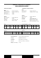
DSL424 TWOPLUSTWO DYNAMICS
DATA SPECIFICATION
Power Requirements 115Volt or 230Volt at 50-60Hz, 15VA
Fuse Type CONFORMS TO IEC127-2.
Fuse Rating 230V=T250mA, 115V=T125mA.
Case Size 482mm (w) x 44mm (h) x 190mm (d)
Weight (incl packaging) 3.7 Kgs
Wideband 22Hz-22kHz CCIR IEC A Q-Pk CCIR
AV -91dB -97dB -97dB -100dB -86dB
RMS -89dB -96dB -99dB
COMPRESSOR / LIMITER CHANNELS
INPUT
Input Impedance 20k Ohms (Balanced)
Max Input level +21dBuB (+17dB ref. +4dBu)
OUTPUT
Output Impedance 50 Ohms (Balanced)
Output Level +20dBu
Bandwidth <12Hz to 35kHz -1dB
Crosstalk @10kHz Better than -80dB
@20kHz Better than -75dB
Output Balance Better than 40dB 20Hz to 10kHz
Noise at Unity Gain ref. +4dBu
Distortion
Wideband 22Hz-22kHz CCIR IEC A Q-Pk CCIR
AV -90dB -98dB -99dB -100dB -88dB
RMS -89dB -96dB -97dB -98dB
100Hz 1kHz 10kHz
Gate Open with +4dB Input <0.04% <0.04% <0.04%
100Hz 1kHz 10kHz
Unity Gain, +4dB Input <0.02% <0.015% <0.035%