Masterflow DC2476 DIGITAL MASTERING PROCESSOR COPYRIGHT This manual is copyrighted 8 2001 by Drawmer Electronics, Ltd. With all rights reserved.
ONE YEAR LIMITED WARRANTY Drawmer Electronics Ltd., warrants the Drawmer DC2476 Digital audio processor to conform substantially to the specifications of this manual for a period of one year from the original date of purchase when used in accordance with the specifications detailed in this manual.
CONTENTS Warranty . . . . . . . . . . . . . . . . . . . . . . . . . . . . . . . . . . . . . . . 2 Contents . . . . . . . . . . . . . . . . . . . . . . . . . . . . . . . . . . . . . . . 3 Safety Consideration . . . . . . . . . . . . . . . . . . . . . . . . . . . . . 4 Radio Frequencies Statement . . . . . . . . . . . . . . . . . . . . . . 4 Chapter 1 - DC2476 Digital Mastering Processor Introduction . . . . . . . . . . . . . . . . . . . . . . . . . . . . . . . . . . . . 5 Audio Connections . . . . . . . . .
DRAWMER DC2476 For the USA DIGITAL MASTERING PROCESSOR FEDERAL COMMUNICATIONS COMMISSION RADIO FREQUENCY INTERFERENCE STATEMENT This equipment has been tested and found to comply with the limits for a Class B digital device, pursuant to Part 15 of the FCC Rules. These limits are designed to provide reasonable protection against harmful interference in a residential installation.
CHAPTER 1 DRAWMER DC2476 DIGITAL MASTERING PROCESSOR INTRODUCTION The Drawmer DC2476 is an extremely sophisticated, all-digital stereo mastering processor designed for use in demanding recording and broadcast applications. Both analogue (balanced XLR) and digital (AES/ EBU and S/PDIF) I/O is provided as standard. The audio converters are 24-bit and the digital output can be either 16, 18, 20 or 24-bit at sample rates of up to 96kHz.
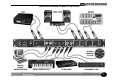
AUDIO CONNECTIONS INSTALLATION PRECAUTIONS Analogue Inputs The inputs and outputs to the DC2476 are electronically balanced and would normally be connected to your system via a patchbay. Should unbalanced operation be required, simply ground pin 3 on the XLR connectors. If earth loop hum problems are encountered, do not disconnect the mains earth but instead, try disconnecting one end of the signal screen on the cables connecting the DC2476 to the patchbay.
INSTALLATION AND CONNECTION GUIDE 7
GETTING STARTED Analogue input. Connect Left and Right input signals via the analogue XLR sockets. The rear panel push switch selects between maximum input levels of +7dBu and +21dBu. This is the level at which the internal analogue electronics will clip, causing distortion, and corresponds to normal -10 and +4dB operating levels. The best noise performance is obtained when the peaks of the input signal are just below the selected maximum level. This can be viewed on the input signal meters.
CHAPTER 2 DC2476 NAVIGATION FINDING YOUR WAY AROUND Despite its high degree of sophistication, the DC2476 has been provided with a friendly and intuitive operating system which uses the same navigation method for all the effect screens. To make the effect screens easier to follow and because there are so many parameters attributed to all the different Effects, these have been arranged so that, where possible, they represent the layout of an equivalent analogue device.
SCREEN NAVIGATION MAP The Effects Screens The Global Screens 10
CHAPTER 3 CONTROL KEY OVERVIEW. PATCH MENU SOURCE This section enables the user to select the internal RAM, the optional S-RAM card or the Factory patches. In addition, effect blocks may be loaded from existing patches and copied into the patch being edited. As delivered, the unit contains 50 preset factory patches that cannot be overwritten as well as 128 memory locations into which user patches may be stored for later use. If the S-RAM card is fitted, a further 128 patches may be stored.
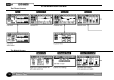
PATCH - LOAD FROM INTERNAL MEMORY Shows the selected page function. Show a selection of patches. Rotate the control knob to scroll through a selection of patches. Push to load. Shows the currently loaded patch. “F:” shows the source of the last patch loaded: C = Card ; F = Factory ; U = User Arrow marks currently loaded patch. Allows a particular block from a patch to be loaded. Allows the user to select either Factory or User Patches. Press the knob to toggle between Fact and User.
PATCH - TOOLS Shows the selected page function. When “Off” is highlighted press knob to toggle between OFF/ON. When Pv is selected (using the Chain/Param button). Use the Left or Right button to move between “MEMORY PROTECTED”, “OFF/ON” “FORMAT CARD” and “READY”. 14 “Write Protect: ON” is also displayed on the “save to card” page. When “READY” is highlighted press knob to format the card.
PATCH - LOAD FROM CARD Shows the selected page function. Show a selection of patches. Shows the card status. Shows the currently loaded patch. “C:” shows the source of the last patch: C = Card ; F = Factory ; U = User Arrow shows currently selected patch. Shows the selected patch. Rotate the control knob to scroll through a selection of patches. Push to load. Allows a particular block from a patch to be loaded. i.e load EQ and Tube Drive only. PATCH - SAVE TO CARD Shows the selected page function.
GLOBAL MENU The Global menu has six sections: Dig I/O, External Clock (XCLK), Word Length and Dither (OUT), Misc, Midi and Sine wave generator (SINE). DIG I/O Dig I/O enables the user to select either the analogue or digital input (both analogue and digital outputs are always active) and the digital input format (AES/EBU or S/PDIF with or without external wordclock sync). Ext sync options should only be selected whenever a wordclock input is present.
GLOBAL - DIGIO When Pv is selected (using the Chain/Param button). Use the Left or Right button to select either the Analogue In SRate, Digital In/Clk or the Output SRate. When the Output SRate is being adjusted the previous value is shown in a black box and the selected value is in a clear box. When the new value has been selected, the old value is cleared and the new box is blackened. Rotate the control knob to the required input signal. Push the control knob to select the function.
GLOBAL - OUT OP Trim is the very last procedure in the effect chain. Rotate the knob to enter the selection. ! Note: The OP TRIM sets an output level which the DC2476 will never rise above. This also occurs when the unit is in bypass mode - so as not to damage sensitive equipment. The “MED” shape is the preferred setting for general purpose. Push the knob to select either Dither Level, Shape , Word Length or OP Trim.. White Noise Dither is shown here.
GLOBAL - MIDI When Pv is selected (using the Chain/Param button). Use the Left or Right button to select either the MIDI RX CHAN or the PROG CHANGE LOADS. When selected push knob to toggle Programme Change on/off. When selected push knob to toggle Continuous Control on/off. When the MIDI RX is selected. Turning the knob changes the MIDI Receive channel 1 - 16 enabling Patch changes to be made via a MIDI device.
CONTROL KEYS LED DISPLAY The main controls keys are: The UP key and the DOWN keys which are used to scroll up or down through the display pages. The LEFT key and the RIGHT key which are used to move along either the CHAIN or the PARAMETER function, depending on which has been selected by the Chain/Param button. Edited Patch This is highlighted when the loaded Patch (User or Factory) has been edited. Midi Active This will display only when the midi interface is in use.
CHAIN / PARAM This switch allows the user to select the required movement of the cursor. With the ACHAIN@ highlighted the cursor manoeuvres through the chain of effects. COMPARE When changes are made to a selected patch, press to Compare the original settings with the new ones. Press again to return to the previous screen. See page 30. FX BYPASS Allows individual effects blocks to be bypassed.
CHAPTER 4 BASIC EFFECTS The signal chain comprises six blocks in addition to the Input and Output sections, which are addressed in exactly the same way as the effects blocks. The DQ and Equaliser blocks are of necessity full-band (they affect the entire signal), while the Expander, Compressor, Limiter and Tube Drive sections that follow are all three-band.
EQUALISER 3 BAND EXPANDER/GATE The equaliser section consists of an analogue modelled 5 band parametric equaliser with a wide range of frequency and bandwidth. Up to 18dB boost or Cut is available on each band. Bass and Treble bands have selectable Shelf or Bell(Peaking) filter shapes whereas the 3 mid bands are bell only. All bell filters have a frequency range from 32Hz to 22kHz in 1 semitone steps. Bandwidth range is from 0.08 octave (1 semitone) to 5 Octaves.
LIMITER AND STEREO IMAGE OUTPUT The three-band limiter is designed to allow peaks signal levels to be controlled without introducing audible side effects unless the amount of limiting is considerable. This may be used to maximize the subjective level of recordings being mastered without affecting the overall sound or peak level, but it is also possible to adjust the release time of individual bands to provide the most transparent results.
INPUT - Page 1 A Gain Reduction bar display will appear if the Gain Management has responded to peaks. This will occur to peaks that exceeD -2dBfs. The dotted line shows the -2dB ceiling. Push the control knob to select either the Left, Right or Both channels for adjustment. Adjust either the Left or Right channel to correct for any stereo image unbalance. Signals levels are displayed over a period of 1-10 Sec. The Bar graph shows the level of digital gain that has been applied to the input signal.
DYNAMIC EQUALISER AND FULL BAND COMPRESSOR The Gain Reduction bar graph shows when the Gain Management has reduced the overall EQ level to avoid any clipping caused by the EQ boost. Shows the amount of compression. i.e. gain added to low level signals. Bar graph shows compressor gain reduction or expander gain. Push the control knob to select either Norm or Filter. Filter is only available when either FREQ or BW is selected. When Pv is selected (using the Chain/Param button).
EQUALISER - Page 1 Push the control knob to select Gain, Frequency or Bandwidth. The Graphical display shows the overall EQ Boost/Cut that has been applied by setting the Gain, Frequency and the Bandwidth.. When Pv is selected. Use the Left or Right button to step along the Parameters of each band. This Marker shows the centre frequency of the selected band. This is the Bar meter showing the Manual Gain Trim level that has been applied.
EXPANDER When Pv is selected. Use the Left or Right button to select either Threshold, Ratio, Attack, Release or Range. Low band Mid band This shows the band settings. High band Push the control knob to select the band to be adjusted. The wider bar shows the threshold for each band. When the two bars meet, the gate is fully open. Thin bars show signal level for each band. BOOTSTRAP COMPRESSOR When Pv is selected. Use the Left or Right button to select either Threshold, Ratio, Attack, Release or Range.
LIMITER AND STEREO IMAGE When Pv is selected. Use the Left or Right button to select either Release or Stereo Image. The gap indicates possible loss of mono information as the image is widened. Push the control knob to select the band to be adjusted. This shows the Low, Mid and High band values for Stereo Image. Excess width Normal width 3 BAND TUBE SATURATION The highlighted brace shows the selected tube band. Push the control knob to select the band to be adjusted.
OUTPUT - Page 1 When Pv is selected (using the Chain/Param button). Use the Left or Right button to select either the Level or the Fader function Shows whether the fader is up or down. Push the control knob to select which band is to be adjusted. Push the control knob to start the Fade Out/ Fade In. This shows the current fade level. Shows G.R applied by the Gain Management after the 3 band signals have been summed. Adjust band levels for correct spectral balance and minimum gain reduction.
Cross-over is common to Expander, Compressor, Limiter/Width and Tube. When in “monitor bands” mode pressing the knob enables you monitor the highlighted band only. CROSSOVER Left/Right toggles between “Moniter Bands” and “Set X-Over”. Push the control knob to toggle through the selections. Rotate the control knob to adjust to the required value. On returning to “set x-over” mode you will still only hear the highlighted band as set in “monitor bands” mode.
CHAPTER 5 OPERATION It is recommended, where possible, to use a digital input source, though in a system comprising a mixture of analogue and digital equipment, the high quality analogue input stage of the DC2476 will yield excellent results. Balanced operation is recommended to eliminate the possibility of ground loop induced hum. In digital systems running from a master word clock, it is generally better to use the DC2476’s word clock input to provide sync.
Both the full band and split band compressors work using Drawmer’s ‘bootstrap’ control system so that as more compression is applied, the overall gain is automatically increased to compensate. Once you are used to this method of working, you’ll find it much more intuitive than the traditional way of working, but you should be prepared to spend a little time experimenting with it in order to get the best out of it.
CHAPTER 6 INFORMATION PRESET FACTORY PATCHES No. 1 2 3 4 5 6 7 8 9 10 11 12 13 14 15 16 17 18 19 20 21 22 23 24 25 34 Preset Name NEUTRAL PATCH CD MASTERFLOW SUBTLE MASTER DE-ESS DE-ESS + SWEET PHAT BOTTOM TIGHT BOTTOM SWEET N PHAT PHAT IN YA FACE ORCHESTRAL CRESCENDO BEEF IT UP BEEF IT UP 2 SPEAK CLEAN UPHILL TUBES DOWNHILL TUBES SMILE TUBES FULL SMILE TUBES PIANO MID LIFT RHYTHM SECTION DRUM KIT WIDE SMILE BOOT BASS GLASSY User Comments No.
USER DEFINED PATCHES No. 1 2 3 4 5 6 7 8 9 10 11 12 13 14 15 16 17 18 19 20 21 22 23 24 25 26 27 28 29 30 31 32 Preset Name No. 33 34 35 36 37 38 39 40 41 42 43 44 45 46 47 48 49 50 51 52 53 54 55 56 57 58 59 60 61 62 63 64 Preset Name No. 65 66 67 68 69 70 71 72 73 74 75 76 77 78 79 80 81 82 83 84 85 86 87 88 89 90 91 92 93 94 95 96 Preset Name No.
Control No 10 11 12 13 14 15 16 17 18 19 20 Effect ---- Reserved ---- Reserved ---- Reserved ---- Reserved Left Gain Right Gain ---- Reserved ---- Reserved ---- Reserved ---- Reserved ---- Reserved 21 22 23 24 25 26 27 28 29 30 DQ Bw DQ Freq DQgain Comp Attack Release ---- Reserved ---- Reserved ---- Reserved ---- Reserved Value Min Max 0 40 0 40 0 0 56 57 58 59 60 61 62 63 64 65 Lo Exp Thresh Lo Exp Ratio Lo Exp Attack Lo Exp Release Lo Exp Range Lo Comp Thresh Lo Comp Ratio Lo Comp Attack Lo Comp R
CHAPTER 7 GENERAL INFORMATION IF A FAULT DEVELOPS CONTACTING DRAWMER For warranty service please call Drawmer Electronics Ltd. or their nearest authorised service facility, giving full details of the difficulty. Drawmer Electronics Ltd., will be pleased to answer all application questions to enhance your usage of this equipment. Please address correspondence to: A list of all main dealers can be found on the Drawmer webpages.
CHAPTER 8 DC2476 DATA PC- Card Interface Connector Standards Card Format Type 1 PCMCIA SRAM card PC-Card 2.0, Jeida 4.0 standard upto 256Kb. SPECIFICATION Internal Battery Analogue Input Connectors Impedance Max. Input Level Input CMR A to D Conversion Dynamic Range Crosstalk XLR Balanced (Pin 2 Hot) 10 KΩ +21 dBu Better than -50dB 24 Bit A/D -112dB Unweighted at 48KHz -80dB @ 10Hz to 20kHz Type Rating Varta Mempac Ni-MH 3.
BLOCK DIAGRAM Ref:2v00 K 21-10-2002 39