
Operating instructions

220V Ultimate Access by Draper Page 4 of 4
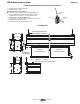
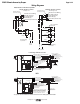
Wiring Diagrams
www.draperinc.com
(765) 987-799
9
MC1
See separate Serial Communication-RS232 Instruction sheet for enabling RS232 with the MC1.
Low Voltage & Wireless Control
Please Note: Do not wire motors in parallel.
Neutral
L1
220v,
50 Hz.
Dashed wiring
by installer
Control
switch
Single Station Control
CE Approved
Junction box at
eft end of screen
Internal Screen Wiring
Blue-220v (Common)
Brown-220v (Down)
Black-220v (Up)
Dashed wiring
by installer
Neutral
Hot
Multiple Station Control
Not CE Approved
Cap off with wire
nut & tape
Red
Red
Red
Blue
Blue
Blue
Black
Black
220v, 50 Hz.
Black
Junction box at
left end of screen
Internal Screen Wiring
Blue-220v (Common)
Brown-220v (Down)
Black-220v (Up)
Green/Yellow (Motor Ground)
Green/Yellow (Motor Ground)
3 Button Wall Switch
DOWN - Black
COM - White
UP - Red
White or Blue-Common to screen & 110/220V AC Neutral
Red-to screen (directional)
Brown-to screen (directional)
Yellow-to 110/220V AC-Hot
Black-to 110/220V AC-Hot
Green/Yellow (Ground)
Eye Port for IR Eye, RF Receiver or LED
Wall Switch. For more than one of
these, a splitter is required.
Aux Port for connecting additional LVC-III
modules (up to six total can be linked-
connect from Aux to Eye).
Dashed wiring by electrician
Low voltage wiring by others
White/Blue (Common)
Red 110/Black 220 (Up)
Black 110/Brown 220 (Down)
Location of key
operated on-off
switch if furnished
To
110/220V
Line
Internal
S
creen Wiring
STOP
Control
Switches
24v DC
STOP
Green/Yellow
(Motor Ground)
RS232 Data FROM Control System
RS232 Data TO Control System
Signal Ground & Manual Switch Common
Manual Switch Down
Manual Switch Up
White or Blue-Common
Red-to Screen (directional)
Black-to Screen (directional)
Brown-Hot to AC
Green/Yellow-Ground
Fuse
Program LED
Eye Port for IR Eye. For RF Receiver or LED
Wall Switch, a Splitter and a Power Supply
is required. Plug RF Receiver or LED Wall
Switch and Power Supply into splitter, then
run cable from Splitter to MC1 Eye Port.
Low Voltage Wiring by others
AC Wiring by electrician
MC1
Location of key
operated on-off
switch if furnished
To AC Line
White/Blue (Common)
Red 110/Black 220 (Up)
Black 110/Brown 220 (Down)
Internal
S
creen Wiring
Green 110V/
Green/Yellow 220V
(Motor Ground)