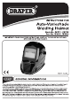
INSTRUCTIONS FOR Auto-Varicose Welding Helmet Stock No. 38271, 38392 Part No. WAUGH, WAUGH IMPORTANT: PLEASE READ THESE INSTRUCTIONS CAREFULLY TO ENSURE THE SAFE AND EFFECTIVE USE OF THIS PRODUCT. C€ 38271 shown [ GENERAL INFORMATION s o These instructions accompanying the product are the original instructions. This document is part of the product peck it for the Rife of the product passing It on to any subsequent hider of the product.
1. TITLE PAGE 1.1 INTRODUCTION: USER MANUAL FOR: AUTO-VARICOSE WELDING HELMET Stock no. 38271, 38392. Part no. WAUGH, WAUGH. 1.2 REVISIONS: Date first published December 2013 As our user manuals are continually updated, users should make sure that they use the very latest version. Downloads are available from: DRAPER TOOLS LIMITED WEBSITE: www.drapertools.com HURLEY ROAD PRODUCT HELPLINE: +44 (0) 23 8049 4344 CHANDLER'S FORD GENERAL FAX: +44 (0) 23 8026 0784 CASTLEREAGH HAMPSHIRE 5053 1YF Uk 1.
2. CONTENTS 2.1 CONTENTS DECLARATION OF CONFORMITY .. PAGE CONTENT TITLE PAGE 1.1 INTRODUCTION .. 12 REVISION HISTORY .. 13 UNDERSTANDING T 14 COPYRIGHT NOTICE CONTENTS 21 CONTENTS GUARANTEE 31 GUARANTEE INTRODUCTION 41 SCOPE 42 SPECIFICATION HEALTH & SAFETY INFORMATION 51 GENERAL SAFETY INSTRUCTIONS FOR WELDING HELMETS. TECHNICAL DESCRIPTION 61 IDENTIFICATION UNPACKING & CHECKING 7. PACKAGING SETTING THE HELMET 1 8. COMFORT AND FIT ADJUSTMENTS 82 BEFORE 83 PRODUCT CHARACTERISTICS.
3. GUARANTEE 3.1 GUARANTEE Draper tools have been carefully tested and inspected before shipment and are guaranteed to be free from defective materials and workmanship for a period of 12 months from the date of purchase except where tools are hired out when the guarantee period is ninety days from the date of purchase. A proof of purchase must be provided with the tool.
4. INTRODUCTION 4.1 SCOPE Professional users helmet with solar powered automatic shading face ies when arc is struck. 4.2 SPECIFICATION Stock no Part no .. Welding filter Permanent protection against UV and IR radiation Power supply Solar cells no batteries required Viewing area UV & IR Protection shade. Optical Class. Shades .. Switching time (Light to dark) . Delay time Filter shades. Weight .
5. HEALTH & SAFETY INFORMATION 5.1 GENERAL SAFETY INSTRUCTIONS FOR WELDING HELMETS Severe burns are possible with a damaged lens (cracks, pits and holes etc). Do not use damaged lenses. Optical radiation can possibly enter in from behind the helmet from other welders welding in the immediate area. This helmet is not designed for oxyacetylene, laser or very low amperage welding applications.
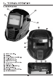
6. TECHNICAL DESCRIPTION 6.1 IDENTIFICATION (@ Outer cover lens. @ Helmet. @ Potentiate control dial. (@ Angle adjustment. (& Upper head band. Circumference adjustment. (@ Head band. Slow-fast delay switch. @ Inner cover len High/low sensitivity switch.
7. UNPACKING & CHECKING 7.1 PACKAGING Carefully remove the helmet from the packaging and examine it for any sign of damage that may have happened during shipping. Lay the contents out and check them against the parts shown below. If any part is damaged or missing; please contact the Draper Helpline {the telephone number appears on the Title page) and do not attempt to use the machine.
8. SETTING THE HELMET 8.1 COMFORT AND FIT ADJUSTMENTS Fig. 1 Push and move strap to obtain correct height. Tums (2 for helmet angle adjustment. Push and turn (8 to vary head size, pull knob again to lock position. Loosen knob to adjust distance from face/eyes. 8.2 BEFORE FIRST USE Tear off the cover lens’ screen film on both sides of the filter cartridge before using the helmet. Adjust and select the desired shade no. according to the type of welding and current of weld to suit your requirements.
8. SETTING THE HELMET 8.4 DARKER SHADE SELECTION FIG. 2 Select the shade level according to the welding process and the value of welding current by turning the potentiate knob (® on the left side of the helmet. The shade number can be manually set between DINS to DIN. Select a shade number by turning the shade adjustment knob until the arrow points to the required setting, see shade guide table on page 12 of this manual. 8.5 SENSITIVITY SELECTION FIG.
8. SETTING THE HELMET 8.7 WELDING/GRINDING FIG. 5 ‘When the helmet is switched to grind function the helmet will only darken enough to provide protection from the glow of ground metal and related sparks.
8. SETTING THE HELMET 8.8 SHADE GUIDE TABLE: ARC Current (Amperes) 40 8 125 175 225 275 350 450 100 | 150 | 200 | 250 | 300 | 400 | 500 [awe TIG, GNAW PAW BB 9110 NOTE: SWAM Shielded Metal Arc Welding. MIG (heavy) MIG on heavy metals. MIG (light} MIG on light alloys. TIG, GNAW Gas Tungsten Arc Welding. Saw Shielded Semi-Automatic Arc Welding. Plasma Arc Cutting.
9. MAINTENANCE Regular inspection and cleaning reduces the necessity for maintenance operations and will keep the product in good working condition. If the replacement of the part is necessary, this has to be done by the manufacturer or his agent in order to avoid a safety hazard. All servicing and maintenance not listed in this manual must be carried out by an approved Draper service agent (see back for contact details).
10. DISPOSAL 10.1 DISPOSAL At the end of the machine’s working life, or when it can no longer be repaired, ensure that it is disposed of according to national regulations. Contact your local authority for details of collection schemes in your area. In all circumstances: . Do not dispose of power tools with domestic waste. Do not incinerate. Do not abandon in the environment. Do not dispose of WERE* — as unsorted municipal waste. * Waste Electrical & Electronic Equipment.
11. EXPLANATION OF SYMBOLS 11.
@[ CONTACTS g et DRAPER TOOLS LIMITED, Hurley Road, Chandler's Ford, Castlereagh, Hampshire. SO 1YF. U.K. Helpline: (023) 8049 4344 Sales Desk: (023) 8049 4333 Internet: www.drapertools.com E-mail: Sales Fax: (023) 8049 4209 General Inquiries: (023} 8026 6355 Repair Agent For after sales servicing or warranty repairs, please contact the Draper Tools Helpline for details of an agent in your local area.