www.dragino.com LSN50v2-D20-D22-D23 LoRaWAN Temperature Sensor Manual Document Version: 2.0 Image Version: v1.7.2 Version Description Date 1.0 Release 2020-Nov-10 1.1 Add power on info and jumper info. 2021-Feb-5 2.
www.dragino.com 1. Introduction .............................................................................................................................. 4 1.1 What is LSN50V2-D20 LoRaWAN Temperature Sensor .............................................................. 4 1.2 Specifications.............................................................................................................................. 5 1.3 Features ....................................................................
www.dragino.com 5.3 How to update the firmware? .................................................................................................. 23 6. Order Info ............................................................................................................................... 24 7. Packing Info ............................................................................................................................ 24 8. Support ......................................................
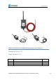
www.dragino.com 1. Introduction 1.1 What is LSN50V2-D2x LoRaWAN Temperature Sensor The Dragino LSN50v2-D2x is a LoRaWAN Temperature Sensor for Internet of Things solution. It can be used to measure the temperature of air, liquid or object, and then upload to IoT server via LoRaWAN wireless protocol. The temperature sensor used in LSN50v2-D2x is DS18B20, which can measure -55°C ~ 125°C with accuracy ±0.5°C (max ±2.0 °C).
www.dragino.com 1.2 Specifications Common DC Characteristics: Supply Voltage: built in 8500mAh Li-SOCI2 battery Operating Temperature: -40 ~ 85°C Temperature Sensor: Range: -55 to + 125°C Accuracy ±0.5°C (max ±2.0 °C). LoRa Spec: Frequency Range, Band 1 (HF): 862 ~ 1020 Mhz 168 dB maximum link budget. High sensitivity: down to -148 dBm. Bullet-proof front end: IIP3 = -12.5 dBm. Excellent blocking immunity. Built-in bit synchronizer for clock recovery.
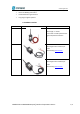
www.dragino.com Wireless Alarm and Security Systems Home and Building Automation Industrial Monitoring and Control Long range Irrigation Systems. 1.5 Hardware Variant Model LSN50v2 D20 Photo Probe Info 1 x DS28B20 Probe Cable Length : 2 meters sensor cable is made by Silica Gel for higher temperature tolerance. LSN50v2 D22 2 x DS28B20 Probes Cable lengths total 1.5meters per probe Cable Drawing: See This Link LSN50v2 D23 3 x DS28B20 Probes Cable lengths total 1.
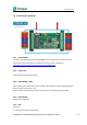
www.dragino.com 1.6 Pin Definitions and Switch 1.6.1 Pin Definition The device is pre-configured to connect to DS18B20 sensor. The other pins are not used. If user want to know more about other pins, please refer the user manual of LSn50v2 at: http://www.dragino.com/downloads/index.php?dir=LSN50-LoRaST/ 1.6.2 Jumper JP2 Power on Device when put this jumper. 1.6.3 BOOT MODE / SW1 1) ISP: upgrade mode, device won't have any signal in this mode. but ready for upgrade firmware. LED won't work.
www.dragino.com 2) Send an uplink packet 1.7 Hardware Change log LSN50v2-D20 v1.0: Release.
www.dragino.com 2. How to use LSN50v2-D20? 2.1 How it works? The LSN50v2-D20 is working as LoRaWAN OTAA Class A end node. Each LSN50v2-D20 is shipped with a worldwide unique set of OTAA and ABP keys. User needs to input the OTAA or ABP keys in the LoRaWAN network server to register. Open the enclosure and power on the LSN50v2-D20, it will join the LoRaWAN network and start to transmit data. The default period for each uplink is 20 minutes. 2.
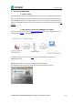
www.dragino.com Input these keys in their LoRaWAN Server portal.
www.dragino.com Step 2: Power on LSN50V2-D20 Step 3: LSN50V2-D20 will auto join to TTN network via the LoRaWAN coverage by DLOS8. After join success, LSN50V2-D20 will start to uplink temperature value to server.
www.dragino.com 2.3 Uplink Payload 2.3.1 Payload Analyze Normal Upload Payload: LSN50v2-D2x use the same payload as LSn50v2 mod1, as below. Size(bytes) Value 2 2 Battery Temp_Red 2 Ignore 1 Alarm Flag 2 Temp_White 2 Temp_Black 当对应端口的 DS18B20 没接或者读数出错时,会显示数据为空.下图是只接 Temp_Red 传感器. Battery: Check the battery voltage.
www.dragino.com If payload is: FF3FH : (FF3F & FC00 == 1) , temp = (FF3FH - 65536)/10 = -19.3 degrees. Alarm Flag & MOD: Example: If payload & 0x01 = 0x01 This is an Alarm Message If payload & 0x01 = 0x00 This is a normal uplink message, no alarm If payload >> 2 = 0x03 means MOD=4, This is a sampling uplink message If payload >> 2 = 0x31 means MOD=31, this message is a reply message for polling, this message contains the alarm settings. see this link for detail. 2.3.
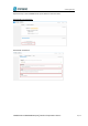
www.dragino.com } else { decode.Temp_Red= parseFloat(((bytes[2]<<24>>16 | bytes[3])/10).toFixed(1)); } if((bytes[7]==0xff)&& (bytes[8]==0xff)) { decode.Temp_White="NULL"; } else { decode.Temp_White=parseFloat(((bytes[7]<<24>>16 | bytes[8])/10).toFixed(1)); } if((bytes[9]==0xff)&& (bytes[10]==0xff)) { decode.Temp_Black="NULL"; } else { decode.Temp_Black=parseFloat(((bytes[9]<<8 | bytes[10])/10) .toFixed(1)); } } else if(mode=='31') { decode.Work_mode="ALARM"; decode.Temp_Red_MIN= bytes[4]<<24>>24; decode.
www.dragino.com decode.Temp_White_MIN= bytes[7]<<24>>24; decode.Temp_White_MAX= bytes[8]<<24>>24; decode.Temp_Black_MIN= bytes[9]<<24>>24; decode.Temp_Black_MAX= bytes[10]<<24>>24; } if(bytes.length==11) { return decode; } 2.4 }Temperature Alarm Feature LSN50V2-D20 work flow with Alarm feature. User can use AT+18ALARM command to set the alarm low limit or high limit. Device will check the temperature every minute, if the temperature lower than low limit or greater than high limit.
www.dragino.com 2.5 Configure LSN50v2-D2x LSN50V2-D20 supports configuration via LoRaWAN downlink command or AT Commands. Downlink command instructions for different platform: http://wiki.dragino.com/index.php?title=Main_Page#Use_Note_for_Server AT Command Access Instructions: LINK There are two parts of commands: General one and Special for this model. 2.5.1 General Configure Commands These commands are to configure: General system settings like: uplink interval.
www.dragino.com Example: AT+18ALARM=-10,30,1 // Alarm when temperature_red < -10 or higher than 30. Downlink Payload: 0x(0B F6 1E 01) // Same as AT+18ALARM=-10,30,1 (note: 0x1E= 30, 0xF6 means: 0xF6-0x100 = -10) Set Alarm Interval: The shortest time of two Alarm packet. (unit: min) AT Command: AT+ATDC=30 // The shortest interval of two Alarm packets is 30 minutes, Means is there is an alarm packet uplink, there won’t be another one in the next 30 minutes.
www.dragino.com 2.6 LED Status LSN50-v2-D2x has an internal LED, it will active in below situation: LED will fast blink 5 times when boot, this means the temperature sensor is detected.传感器接线检测 LED 闪烁删除,改成用串口看. After the fast blinks on boot, the LED will flash once which means device is trying to send Join Packet to the network. If device successful join LoRaWAN network, the LED will be solid on for 5 seconds. 2.7 Button Function Internal RESET button: Press this button will reboot the device.
www.dragino.com 3. Battery & how to replace 3.1 Battery Type LSN50V2-D2X is equipped with a 8500mAH ER26500 Li-SOCI2 battery. The battery is un-rechargeable battery with low discharge rate targeting for 8~10 years use. This type of battery is commonly used in IoT target for long-term running, such as water meter. The discharge curve is not linear so can’t simply use percentage to show the battery level. Below is the battery performance. Minimum Working Voltage for the LSN50V2-D2X: LSN50V2-D2X: 2.45v ~ 3.
www.dragino.com Instruction to use as below: Step 1: Downlink the up-to-date DRAGINO_Battery_Life_Prediction_Table.xlsx from: https://www.dragino.com/downloads/index.php?dir=LoRa_End_Node/Battery_Analyze/ Step 2: Open it and choose Product Model Uplink Interval Working Mode And the Life expectation in difference case will be shown on the right.
www.dragino.com 3.3.2 Replace the battery You can change the battery in the LSN50V2-D2X.The type of battery is not limited as long as the output is between 3v to 3.6v. On the main board, there is a diode (D1) between the battery and the main circuit. If you need to use a battery with less than 3.3v, please remove the D1 and shortcut the two pads of it so there won’t be voltage drop between battery and main board. The default battery pack of LSN50V2-D2X includes a ER26500 plus super capacitor.
www.dragino.com 4. Use AT Command 4.1 Access AT Command User can use a USB to TTL adapter to connect to LSN50V2-D20 to use AT command to configure the device.
www.dragino.com 5. FAQ 5.1 What is the frequency range of LSN50v2-D20? Different LSN50V2-D20 version supports different frequency range, below is the table for the working frequency and recommend bands for each model: Version LoRa IC Working Frequency Best Tune Recommend Bands Frequency 433 SX1278 Band2(LF): 410 ~525 Mhz 433Mhz CN470/EU433 868 SX1276 Band1(HF):862~1020 Mhz 868Mhz EU868/IN865/RU864 915 SX1276 Band1(HF):862 ~1020 Mhz 915Mhz AS923/AU915/ KR920/US915 5.
www.dragino.com 6. Order Info Part Number: LSN50V2-D20-XXX (Signal Probe) Or LSN50V2-D22-XXX (Dual Probe) Or LSN50V2-D23-XXX (Triple Probe) XXX: The default frequency band AS923: LoRaWAN AS923 band AU915: LoRaWAN AU915 band EU433: LoRaWAN EU433 band EU868: LoRaWAN EU868 band KR920: LoRaWAN KR920 band US915: LoRaWAN US915 band IN865: LoRaWAN IN865 band CN470: LoRaWAN CN470 band 7.