DR® TRIMMER/MOWER™ SAFETY & OPERATING INSTRUCTIONS Models: SPRINT®, PRO, and PRO-XL SELF-PROPELLED Serial No. Order No. Original Language DR Power Equipment Toll-free phone: 1-800-DR-OWNER (376-9637) Fax: 1-802-877-1213 Website: www.DRpower.com Read and understand this manual and all instructions before operating the DR TRIMMER/MOWER.
Table of Contents Chapter 1: General Safety Rules............................................................................................................................................................ 3 Chapter 2: Setting Up The DR TRIMMER/MOWER ............................................................................................................................ 6 Chapter 3: Operating The DR TRIMMER/MOWER ............................................................................................
Chapter 1: General Safety Rules Read this safety & operating Instructions manual before you use the DR TRIMMER/MOWER. Become familiar with the operation and service recommendations to ensure the best performance from your machine. If you have any questions or need assistance, please contact us at www.DRpower.com or call toll-free 1-800-DR-OWNER (376-9637) and one of our Technical Support Representatives will be happy to help you.
Operating the Mower Safely This is a high-powered machine, with moving parts operating with high energy at high speeds. You must operate the machine safely. Unsafe operation can create a number of hazards for you, as well as anyone else in the nearby area. Always take the following precautions when using this machine: Never allow people who are unfamiliar with these instructions to use the DR TRIMMER/MOWER.
Safety with Gasoline - Powered Machines Gasoline is a highly flammable liquid. Gasoline also gives off flammable vapor that can be easily ignited and cause a fire or explosion. Never overlook the hazards of gasoline. Always follow these precautions: Never run the engine in an enclosed area or without proper ventilation as the exhaust from the engine contains carbon monoxide, which is an odorless, tasteless, and deadly poisonous gas.
Chapter 2: Setting Up The DR TRIMMER/MOWER It may be helpful to familiarize yourself with the controls and features of your DR TRIMMER/MOWER as shown in Figure 1 before beginning these procedures. If you have any questions at all, please feel free to contact us at www.DRpower.com.
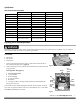
Specifications MECHANICAL SPECIFICATIONS Engine Series Torque Fuel Capacity Oil Capacity Air Filter Oil Filter Wheels Frame Cutting Width Cutting Height Machine Width Machine Weight 6.25 Sprint Briggs & Stratton Quantum 6.25 ft. lbs.(8.5 Nm) 1.5 Quarts (1.4 Liters) 1.25 pints (0.59 Liter) Pleated Paper NA 14" Resin 14-Gauge Steel 20" 1-1/2" to 4" 23" 68 lbs. Manual Start, 75 lbs. Electric Start 6.75 PRO Briggs & Stratton Quantum 6.75 ft. lbs.(9.1 Nm) 1.5 Quarts (1.4 Liters) 1.25 pints (0.
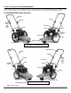
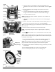
Top Rear Insert Handlebar Hand Knobs Wheel Cable Ties Handlebar MowBall™ Package Frame Nose Insert Product Package Figure 4 3. Use Wire Cutters to cut the Cable Ties that attach the Wheels to the Handlebar and the Cable Tie that secures the Handlebar to the Box (Figure 4). 4. Remove the Wheels, Product Package and Top Rear Insert from the Shipping Box. 5. Loosen the Handlebar Adjusting Knobs and rotate the Handlebar up enough to remove the Frame Nose Insert and Mow-Ball™ Package. 6.
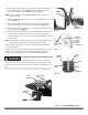
15. Lift the Upper Handlebar until it is near the operator position and tighten the Handlebar Adjuster Knobs (Figure 8) (see the Safety & Operating Instructions manual for more handlebar adjustment details). NOTE: Ensure that the teeth of the Handlebar Adjuster mesh correctly as you tighten the Knobs. Meshing Teeth 16. Open the Product Package and remove the Trimmer Head Locking Tool and literature (Figure 9). 17.
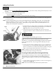
Adding Oil and Gasoline You must add oil before starting the engine. This machine is shipped without oil. Traces of oil may be in the reservoir from factory testing, but you must add oil before starting the engine. Fill the reservoir slowly, checking the level frequently to avoid overfilling. To get an accurate reading when checking the oil level: - the machine should be on a level surface. - the dipstick should be screwed down to ensure an accurate oil level reading.
Adjusting the Handlebar It is important to find a Handlebar height that allows the Mow-Ball Support to glide along the ground and remain balanced so you do not have to push down or pull up on the Handlebar. Upper Handlebar Lower Handlebar Bolt At the proper height, your hands should rest at a comfortable level and the front end of the Trimmer should glide easily on the Mow-Ball Support as shown in Figure 25 on page 16. You may find you like different Handlebar heights for different mowing conditions.
Chapter 3: Operating The DR TRIMMER/MOWER You may find it helpful to review the DR TRIMMER/MOWER Controls and Features (Figure 1 on page 6) before reading this chapter. The design of your machine is for trimming and mowing grass, weeds, and other growth as specified in this manual. Do not use it for any other purpose as it could cause serious injury. Contact with internal rotating parts will cause serious personal injury.
NOTE: Do not engage the Bail Bar (Trimmer Head Control) until after the Engine has started. Stopping the Engine 1. Move the Throttle Control Lever (Figure 1 on page 6) all the way back past the TURTLE (Slow) position to the STOP position. NOTE: If you have an Electric-Starting model, please note that the Key does not stop the Engine. You must follow these instructions to stop the Engine for both Electric and Manual-Starting models. 2. Remove the Key for safety.
NOTE: In PTA mode, the Trimmer’s Wheels stay straight while the Trimmer Head tilts (Figure 16). The Cutting Cords extend beyond the wheelbase in the PTA mode (Figure 16), allowing you to easily cut under obstacles. The Trimmer Head and the Cutting Cords also tilt slightly in PTA mode so you can edge and trim along gardens, paths, and driveways (Figure 16).
The DR TRIMMER/MOWER Cutting Cords Same on This Side Before performing any adjustment, maintenance procedure or inspection, stop the engine, wait five (5) minutes to allow parts to cool and disconnect the spark plug wire, keeping it away from the spark plug. Running the trimmer with only one cord installed, or cords installed at other than 180 degrees apart can cause excessive vibration and may damage the machine.
Cord Tips We ship two (2) thicknesses of Cutting Cord with your DR TRIMMER/MOWER. The Cords are Blue (175-mil) and Green (155-mil). Because conditions and vegetation vary so much, you should experiment with Cord weights (diameters) to discover what works best for your particular mowing and trimming situations. Here are a few things to keep in mind: If you buy Cutting Cord in rolls, cut it in 23" lengths. Cord life depends on trimming conditions. Replace Cords when they become broken or frayed.
Obstacle Tips Dealing with obstacles in the terrain is easy with your new DR TRIMMER/MOWER. The following section explains how to approach most common obstacles. The trimmer engine's power can easily throw stones, sticks, and other debris at great velocity, which could cause personal injury or property damage. Do not run the machine over gravel driveways or over loose stones or mulch with the trimmer head spinning. Tip: The DR TRIMMER/MOWER discharges cut material to the right.
Wet Conditions Make sure of your footing when operating in wet conditions. Because there is no housing to restrict the flow of cut material, you can also use your DR TRIMMER/MOWER to mow wet or heavy growth. You can use the DR in damp conditions, after a rain, or in the early morning dew without clogging or stalling. You can also mow wet areas such as ditches and around ponds (Figure 28). NOTE: NEVER mow in the rain. Water on the Spark Plug may cause the Engine to stall.
Chapter 4: Maintaining The DR TRIMMER/MOWER Regular maintenance is the way to ensure the best performance and long life of your machine. Please refer to this manual and the engine manufacturer's owner's manual for maintenance procedures. Service intervals listed in the checklist below supersede those listed in the engine manufacturer's owner's manual. Before performing any maintenance procedure or inspection, stop the engine, wait five (5) minutes to allow all parts to cool.
2. Looking down at the top of the Frame, turn the Mow-Ball™ Support Assembly clockwise until it unscrews completely from the Bearing Housing (Figure 30). Remove the Tool or Screwdriver after you have removed the Mow-Ball™ Support Assembly. NOTE: If the Mow-Ball™ Support Assembly continues to turn, but does not come off, check to be sure that you locked the Head Locking Tool or Screwdriver into the shaft. 3. To reinstall the Mow-Ball™ Support Assembly, reverse the above instructions.
Remove Screws Tool needed: 3/8" Wrench 1. Remove the screws on either side of the Stone Guard and drop it from the Frame (Figure 32). Tip: Keep the screws together with the Stone Guard. Removing and Replacing Section: Bottom Shield - SPRINT and PRO Models Figure 32 Before performing any maintenance procedure or inspection, stop the engine, wait five (5) minutes to allow all parts to cool. Disconnect the spark plug wire, keeping it away from the spark plug.
Side Shield Bottom Shield 3. Remove the fourth mounting Bolt and Washer from the front of the Frame on the outer edge near the Bearing Housing (Figure 34) using a 3/8" Wrench or Socket. 4. Remove the Bottom Shield by sliding it out from under the Side Shield and lifting it up and over the Bearing Housing (Figure 34). 5. Reinstall the Bottom Shield in the reverse order.
Drive Belt – PRO-XL SELF-PROPELLED Before performing any maintenance procedure or inspection, stop the engine, wait five (5) minutes to allow all parts to cool. Disconnect the spark plug wire, keeping it away from the spark plug. Use only DR belts on your machine. Do not use hardware store variety belts. Tools and Part needed: Transmission Pulley 7/16" Wrench 3/8" Wrench DR Drive Belt #179581 1. Remove the Mow-Ball™ Support Assembly. See “Removing the Mow-Ball™ Support Assembly” on page 19. 2.
Tools needed: Actuator Rod 3/8" Socket 7/16" Wrench 1/2" Wrench 1. Remove the Mow-Ball™ Support Assembly. See “Removing the Mow-Ball™ Support Assembly” on page 19. 2. Remove the Stone Guard Flap. See “Removing the Stone Guard Flap” on page 20. This step is not applicable to the Self-Propelled model. Lock Nut 3. Remove the Bottom Shield. See “Bottom Shield” on page 21. 4. Using a 3/8" Socket, remove the Lock Nut from the Brake Actuator Rod and remove the Rod from the Brake Arm (Figure 39).
Wheels - SPRINT and PRO Models Remove Locknut Before performing any adjustment, maintenance procedure or inspection, stop the engine, wait five (5) minutes to allow parts to cool and disconnect the spark plug wire, keeping it away from the spark plug. Tool needed: 5/8" Wrench 1. Block and stabilize the machine so that the Wheels are off the ground. 2. Loosen and remove the Locknut (Figure 43). Figure 43 3. Slide the Wheel off the Axle. 4. Reverse the steps to install the Wheel.
NOTE: The new Wheel will have a red Sleeve inside the Hub. This Sleeve keeps the Wheel Splines in place during shipment. As the Wheel moves onto the Axle, the Sleeve will push out of the Wheel Hub. You can then remove and discard the Sleeve. 8. Install the Axle Nut and tighten it firmly. The installation is now complete. NOTE: You have properly installed the Wheel when the Wheel locks against the Axle when you pull the Trimmer backward, and will freewheel when pushed forward.
If the machine will not drive forward: Grasp the Lower Section of the Cable Adjuster with one hand and hold firmly. Turn the Upper Section of the Cable Adjuster clockwise so that the Adjuster is lengthening or turning apart. Make one revolution of the Adjuster at a time until the drive engages and disengages properly (Figure 48). If the machine creeps ahead or “walks”: Grasp the Lower Section of the Cable Adjuster with one hand and hold firmly.
Battery Care (Electric-Start Models) Proper care can extend the life of a battery. Follow these recommendations to ensure your Battery’s best performance and long life: Before charging the Battery, observe its external appearance and keep it clean and dry. Never charge or use a Battery that shows cracks, changes shape, leaks, or otherwise obviously damaged. Do not allow the Battery to run down completely before charging. Leaving the Battery discharged damages the Battery.
Recycling a Used Battery Please dispose of used batteries responsibly, according to your local hazardous materials regulations. Never throw away used batteries in your household trash. Please dispose of your used Batteries responsibly by recycling them. Call your local Solid Waste Management District or your local waste handler to locate the collection site nearest you. Some collection sites recycle Batteries year-round; others collect them periodically.
If your DR TRIMMER/MOWER will be idle for more than 30 days, we recommend using a gas stabilizer. This will prevent sediment from gumming up the Carburetor. If there is dirt or moisture in the gas or Tank, remove it by draining the Tank. Completely fill the Tank with fresh, unleaded gas and add the appropriate amount of stabilizer or gasoline additive. Run the Engine for a short time to allow the additive to circulate.
Chapter 5: Troubleshooting Most problems are easy to fix. Consult the Troubleshooting Table below for common problems and their solutions. If you continue to experience problems, contact us at www.DRpower.com or call toll-free 1-800-DR-OWNER (376-9637) for support. Before performing any maintenance procedure or inspection, stop the engine, wait five (5) minutes to allow all parts to cool. Disconnect the spark plug wire, keeping it away from the spark plug.
Before performing any maintenance procedure or inspection, stop the engine, wait five (5) minutes to allow all parts to cool. Disconnect the spark plug wire, keeping it away from the spark plug. Troubleshooting Table (Continued) SYMPTOM POSSIBLE CAUSE The Engine won’t start using Electric-Start. Check all of the items under the section called Electric Starting on page 12 and the previous section on Manual Starting.
Before performing any maintenance procedure or inspection, stop the engine, wait five (5) minutes to allow all parts to cool. Disconnect the spark plug wire, keeping it away from the spark plug. Troubleshooting Table (Continued) SYMPTOM POSSIBLE CAUSE The Trimmer Head keeps spinning or spins when you release the Bail Bar. Check for proper alignment of the V-Belt. Check it against Figure 35 in the “Trimmer Head Belt-All Models” on page 22.
Before performing any maintenance procedure or inspection, stop the engine, wait five (5) minutes to allow all parts to cool. Disconnect the spark plug wire, keeping it away from the spark plug. Troubleshooting Table (Continued) 34 SYMPTOM POSSIBLE CAUSE The Drive Wheels won’t turn (SELFPROPELLED model). The Transmission Clutch may be out of adjustment. Adjust the Inline Adjuster located in the Clutch Cable. See “Adjusting the Wheel Clutch” on page 27.
Notes: CONTACT US AT www.DRpower.
Chapter 6: Parts Lists, Schematic Diagrams And Warranty Parts List - Handlebar Assembly - SPRINT and PRO Models NOTE: Part numbers listed are available through DR Power Equipment.
Schematic - Handlebar Assembly - SPRINT and PRO Models 061213 CONTACT US AT www.DRpower.
Parts List - Axle Assembly - SPRINT and PRO Models NOTE: Part numbers listed are available through DR Power Equipment.
Schematic - Axle Assembly - SPRINT and PRO Models 050919 CONTACT US AT www.DRpower.
Parts List - Main Frame Assembly - All Models NOTE: Part numbers listed are available through DR Power Equipment.
Schematic – Main Frame Assembly - All Models 061212 CONTACT US AT www.DRpower.
Parts List - Handlebar Assembly – PRO-XL SELF- PROPELLED NOTE: Part numbers listed are available through DR Power Equipment. Ref# Part# Description Ref# Part# Description 03 04 05 143971 112381 113081 18 190471 19 143931 06 07 08 09 09.1 10 11 12 13 14 15 174561 144641 110761 147551 191911 123361 174531 110731 101451 112371 143681 20 21 22 22.1 23 24 25 26 27 28 143661 191351 143731 145801 112141 179641 114561 190011 179651 214661 Grip, Handlebar, Textured Vinyl, 18-3/4" Long Spring, C, .
Schematic - Handlebar Assembly – PRO-XL SELF- PROPELLED 061213 CONTACT US AT www.DRpower.
Parts List - Axle Assembly – PRO-XL SELF- PROPELLED NOTE: Part numbers listed are available through DR Power Equipment. Ref# Part# Description Ref# Part# Description 02 08 12 14 46 50 57 68 76 77 78 190541 110761 110731 112371 179581 111581 175601 118731 193801 189791 112441 179121 213101 143751 179611 152331 240321 193811 87 189591 88 179631 89 179591 90 152501 91 179551 92 175521 93 193791 94 193821 95 179681 96 180841 97 179621 99 213181 Not Illustrated Spring, Ext.
Front Rear Schematic - Axle Assembly - SELF- PROPELLED 080513 CONTACT US AT www.DRpower.
Parts List - Mow Ball™ Assembly - All Models NOTE: Part numbers listed are available through DR Power Equipment. Ref# Part# Description Ref# Part# Description 14 30 31 112371 213081 143991 41 42 43 44 235151 143551 143541 144701 32 33 34 143511 121521 114781 Washer, Flat, #10 USS Bolt, Flat Head, 5/16"-18 x 2.75" w/Patch Spring, Ext., .500" OD x .049" Wire, Brake Return Brake Arm Assembly Washer, Axle, .750" OD x .
Schematic – Mow Ball™ Assembly - All Models 080513
Notes:
Notes:
Notes: 75 MEIGS ROAD, P.O. BOX 25, VERGENNES, VERMONT 05491 ©2010 Country Home Products, Inc.
DR® TRIMMER/MOWER 2-Year Limited Warranty Terms and Conditions The DR TRIMMER/MOWER is warranted for two (2) years against defects in materials or workmanship when put to ordinary and normal consumer use; ninety (90) days for any other use. The engine manufacturer warrants the engine separately. For the purposes of all the above warranties, “ordinary and normal consumer use” refers to non-commercial residential use and does not include misuse, accidents or damage due to inadequate maintenance.
Daily Checklist for the DR TRIMMER/MOWER Before performing any maintenance procedure or inspection, stop the engine, wait five (5) minutes to allow all parts to cool. Disconnect the spark plug wire, keeping it away from the spark plug. To help maintain your DR TRIMMER/MOWER for optimum performance, we recommend you follow this checklist each time you use your machine.