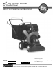
DR® LEAF and LAWN VACUUM Self Propelled Model SAFETY & OPERATING INSTRUCTIONS Serial No. Order No. Original Language DR Power Equipment Toll-free phone: 1-800-DR-OWNER (376-9637) Fax: 1-802-877-1213 Website: www.DRpower.com Read and understand this manual and all instructions before operating the DR LEAF and LAWN VACUUM.
Table of Contents Chapter 1: General Safety Rules............................................................................................................................................................ 3 Chapter 2: Setting Up The DR® LEAF and LAWN VACUUM............................................................................................................... 7 Chapter 3: Operating The DR LEAF and LAWN VACUUM............................................................................................
Chapter 1: General Safety Rules Read this safety & operating Instructions manual before you use the DR LEAF AND LAWN VACUUM. Become familiar with the operation and service recommendations to ensure the best performance from your machine. If you have any questions or need assistance, please contact us at www.DRpower.com or call toll-free 1-800-DR-OWNER (376-9637) and one of our Technical Support Representatives will be happy to help you.
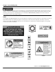
Protecting Yourself and Those Around You This is a high-powered machine, with moving parts operating with high energy at high speeds. Use proper clothing and safety gear when operating this machine to prevent or minimize the risk of severe injury. You must operate the machine safely. Unsafe operation can create a number of hazards for you, as well as anyone else in the nearby area.
Safety with Gasoline-Powered Machines Gasoline is a highly flammable liquid. Gasoline also gives off flammable vapor that can be easily ignited and cause a fire or explosion. Never overlook the hazards of gasoline. Always follow these precautions: Never run the engine in an enclosed area or without proper ventilation as the exhaust from the engine contains carbon monoxide, which is an odorless, tasteless, and deadly poisonous gas.
General Safety Operating this vacuum safely is necessary to prevent or minimize the risk of death or serious injury. Unsafe operation can create a number of hazards for you. Always take the following precautions when operating this vacuum: Keep in mind that the operator or user is responsible for accidents or hazards occurring to other people, their property, and themselves. Your DR walk-behind leaf & lawn vacuum is a powerful tool, not a plaything. Exercise extreme caution at all times.
Chapter 2: Setting Up The DR® LEAF and LAWN VACUUM It may be helpful to familiarize yourself with the controls and features of your DR LEAF and LAWN VACUUM as shown in Figure 1 before beginning these procedures. If you have any questions at all, please feel free to contact us at www.DRpower.com.
Specifications Manual Start See Engine Owners Manual Direct Drive 145 MPH Hardened Tool Steel 2" 5/8" to 4" 4 bushel 3 forward, 1 reverse 67" 43" 25.5" 210 Lbs Engine Impeller Drive Method Impeller Speed Chipper Knife Material Chipping Capacity Height Adjustment Range Collection Bag Volume Gears Overall Length Overall Height Width Machine ship Weight Electric Start See Engine Owners Manual Direct Drive 145 MPH Hardened Tool Steel 2" 5/8" to 4" 4 bushel 3 forward, 1 reverse 67" 43" 25.
Hardware Bag Contents (Figure 4 and Table Below) ITEM# 1 2 3 4 5 6 7 8 9 10 11 12 13 14 15 16 17 PART # 143401 284701 149651 167791 146051 144181 143131 149451 154821 285641 145861 155121 155111 145151 154801 285631 285651 DESCRIPTION Nut, Nylon Lock, 1/4-20 Bolt, Hhcs, 1/4-20 x 2-1/4" Washer, Fender, 5/16" Bolt, Hhcs, 5/16-18 x 3/4" Bolt, Hhcs, 5/16-18 x 1" Locknut, Whiz, 5/16-18 Nut, Nylon Lock, 5/16-18 Hook, Bag Hanger Eyebolt, 5/16-18 x 5" Knob, Hand, 5/16-18 Cotter Pin, Hair Spring Screw, Self Tappin
3. Take the Upper Handle Bar Assembly with the Bail on top and slide the flat ends of the Upper Handle inside the Lower Handle. Secure with four 5/1618 x 1" Bolts and four 5/16-18 Nylon Locknuts (Figure 7). Lower Handlebar 4. Locate the Clutch Cable, which is attached to the LLV machine on the right hand side. Slip the eyelet end on to the front Bail Bar Hook (Figure 8). Bolts and Locknuts Bail Bolts and Locknuts Upper Handlebar 5.
Bag Hanger Hook with Wiz nut 9. Locate the two Carabiners, three Bag Hanger Hooks and four 5/16-18 Wiz Nuts included in the Bolt Bag. Mount the two upper Hooks through the upper holes in the Handlebar Assembly with the Hooks on the inside (Figure 11). Secure with a Wiz Nut on the outside of the Upper Handlebar. Upper Handlebar 10. Thread a Wiz Nut onto the one remaining Hook as far as it will go on the threads so that the flat side of the Nut is facing away from the Hook (See detail). Carabiner 11.
17. Locate the two Bag Hanger Straps on the rear (zipper end) of the Bag. Attach the two Straps to the Hooks near the top of the Handlebar (Figure 16). Rear Bag Hanger Straps 18. Locate the three Bag Hanger Straps on the front of the Bag and hang them on the Hook on the right side and to the two Carabines at left and center of the Bag Hanger Frame. Front Bag Hanger Straps 19. Slip the Bag Inlet Neck over the Discharge Tube (Figure 17). 20.
Chapter 3: Operating The DR LEAF and LAWN VACUUM It may be helpful to better familiarize yourself with the features of your DR LEAF and LAWN VACUUM by reviewing Figure 1 in Chapter 2 before beginning the steps outlined in this chapter. Always refer to the Engine manual for more specific Engine information. Fuel Shut Off Choke Starting the Engine (manual Start) On/Off Switch 1. Make sure the Shift Rod is in the N (Neutral) position. 2.
Shift to N (Neutral) before starting the engine and whenever the machine is stopped. Shift to R (Reverse) to move the machine in a reverse direction (.8 MPH). Shift to N (Neutral) to move the machine when the engine is not running (free wheeling). 1st gear is the slowest speed and is used when vacuuming in difficult conditions such as heavy leaf drop, damp leaves. 2nd gear is a medium speed and used for average conditions. This is the gear you should use most of the time.
Bag Maintenance Keep the bag clean by occasionally washing it by hand with mild soap and water. A clean bag improves air flow and results in better vacuuming performance. Do not wash the bag in an automatic washer. Do not use a cleaner which contains bleach. Allow the bag to dry thoroughly before storing. Installation Of The Bag 1. Locate the two bag hanger straps on the rear (zipper end) of the bag. Attach the two straps to the hooks near the top of the handlebar. 2.
Operating Safety The operation of any LEAF and LAWN VACUUM can result in foreign objects being thrown into the eyes, which can result in severe eye damage. Always wear the safety glasses provided with the LEAF and LAWN VACUUM or eye shields before chipping or while performing any adjustments or repairs. Only operate your LEAF and LAWN VACUUM from the rear or from the chipper side.
Avoid overfilling the vacuum snout. This will cause clogging. Wet and soggy material will also cause clogging. A steady, smaller flow of materials provides the most effective results. The bag should not be removed for emptying, simply unzip and dump leaves out. If you wish to move or bag leaves, dump onto a tarp. Avoid clogging when vacuuming loose, stringy material such as hay or pine straw, by picking up a small amount at a time. Check and empty the collection bag frequently.
Chapter 4: Maintaining The DR LEAF and LAWN VACUUM Regular maintenance is the way to ensure the best performance and long life of your machine. Please refer to this manual and the engine manufacturer's owner's manual for maintenance procedures. Service intervals listed in the checklist below supersede those listed in the engine manufacturer's owner's manual.
5. Remove the two Nuts from the Hopper Studs (Figure 26). 6. Hold the Bolt Head inside the Housing in place with a 1/2" Wrench or locking Pliers as you remove the Low Profile Locknut (Hopper side) and Hopper together. The Bolt can be left in the Housing. 7. Rotate the Flywheel so the Knife hardware can be accessed from the oval cutout you removed the Hopper from. 8. Use a 3/16" Allen Wrench (Hopper side) and a 1/2" Wrench (Flywheel side) to remove the Knife from the Flywheel. 9. Replace or sharpen knife.
Chapter 5: Vacuum Kit #284221 Shut down the engine, remove the spark plug wire and wait 5 minutes for parts to cool before performing before installing the Vacuum Kit. 1 Tools Needed: 2 5 3 5/16" Wrench 7/16" Wrench Short Flat Head Screwdriver Wire Cutters Utility Knife 1. Cut the Tape on the Box Flaps with a Utility Knife. 6 2. Remove the parts from the Box and lay them out on a flat clean area.
4. Place the Vacuum Adapter onto the front of the Housing (Figure 32) so the studs are located in the right hand side of the lower slots (Detail A). Slide the Adapter to the right and down so the Plunger Bracket on the Adapter pushes the Safety Switch in (Detail B). 5. Install four 5/16-18 Hand Knobs, with the Cable Guide under the top Knob, onto the studs to secure the Vacuum Adapter. Hand Knobs Cable Guide Detail A Safety Switch Plunger Bracket Vacuum adapter Detail B Figure 32 6.
Chapter 6: Troubleshooting Most problems are easy to fix. Consult the Troubleshooting Table below for common problems and their solutions. If you continue to experience problems, contact us at www.DRpower.com or call toll-free 1-800-DR-OWNER (376-9637) for support. Shut down the engine, remove the spark plug wire and wait 5 minutes for parts to cool before performing any maintenance procedure or inspection on the Machine.
Troubleshooting Table (Continued) Shut down the engine, remove the spark plug wire and wait 5 minutes for parts to cool before performing any maintenance procedure or inspection on the vacuum. SYMPTOM POSSIBLE CAUSE ; CORRECTIVE ACTION Loss of traction Gear shift lever does not shift Wheels do not stop when Wheel Drive Bail Cable is released Product build-up in shredding chamber. Drive belt loose; Adjust wheel drive bail cable. Stretched or broken drive belt; Replace belt.
Chapter 7: Parts Lists, Schematic Diagrams And Warranty Parts List – MAIN ASSEMBLY NOTE: Part numbers listed are available through DR Power Equipment.
Schematic – MAIN ASSEMBLY CONTACT US AT www.DRpower.
Parts List – DRIVE TRAIN ASSEMBLY NOTE: Part numbers listed are available through DR Power Equipment. Ref# Part# Description Ref# Part# Description 01 02 03 04 Base Weldment, Engine Side Weldment, Left Side Weldment, Right Engine, B&S, MS Engine, B&S, ES Engine, B&S, MS, CA Engine, B&S, ES, CA Transmission Washer, Shift Lever Arm, Transmission Chain, #40, .
Schematic – DRIVE TRAIN ASSEMBLY CONTACT US AT www.DRpower.
Parts List and Schematic – OPTIONAL VACUUM KIT #284221 NOTE: Part numbers listed are available through DR Power Equipment. Ref# Part# Description Ref# Part# Description 01 02 03 04 05 06 07 Adapter, Vacuum Clamp, Hose, 6-1/8" Hose, 6" Dia.
Notes: CONTACT US AT www.DRpower.
Notes: 30 DR® LEAF AND LAWN VACUUM
DR® LEAF AND LAWN VACUUM 2-Year Limited Warranty Terms and Conditions The DR LEAF AND LAWN VACUUM is warranted for two (2) years against defects in materials or workmanship when put to ordinary and normal consumer use; ninety (90) days for any other use. For the purposes of all the above warranties, “ordinary and normal consumer use” refers to non-commercial residential use and does not include misuse, accidents or damage due to inadequate maintenance.
Daily Checklist for the DR LEAF and LAWN VACUUM To help maintain your DR LEAF and LAWN VACUUM for optimum performance, we recommend you follow this checklist each time you use your machine. Shut down the engine, remove the spark plug wire and wait 5 minutes for parts to cool before performing any maintenance procedure or inspection on the Machine. [ ] Check the engine oil level. [ ] Check Fuel Level [ ] Check the general condition of the Vacuum, e.g.; nuts, bolts, welds, etc.