
Operating instructions


16 DR
®
RAPIDFIRE™ LOG SPLITTER
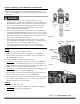
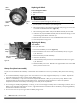
3. Remove the Bolt, Lock Washer and large Flat Washer from the Clutch with a
1/2" Wrench and remove the Clutch from the Engine Shaft (Figure 27).
Note: To remove and replace the Clutch hardware, use a dead blow hammer to hit
the Wrench to enable you to create torque and prevent movement of the Engine
Shaft.
4. Install the new Clutch and secure with the Bolt, Lock Washer and large Flat
Washer with a 1/2" Wrench.
5. Install the Belts and Belt cover.
Replacing the Linkage Bushings (For excessive play in bushings)
Tools and Supplies needed:
3/16" Allen Wrench
Retaining-ring Pliers
Hammer and long Punch
1. Remove Belt Cover as described in “Changing and Adjusting Belts” (page
17).
2. Remove the Belts by rolling them off the Flywheels as you slowly rotate the
Flywheels (Figure 26).
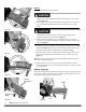
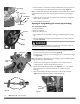
3. Loosen the Set Screws on the Flywheel Hubs and with help from another
person pull the Flywheels from the Shafts (Figure 28).
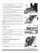
4. Use Retaining-ring Pliers to remove the Rings from one side of both Linkage
Pins (Figure 29).
Note: Pay attention to the positioning of the Linkage for proper installation of the
Linkage assembly (step 7) when finished.
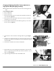
5. Use a Hammer and long Punch to push the Pins out of the Frame and
Linkage assembly. Pull the Linkage from the machine.
6. Replace the used Bushings with new ones (Figure 30). You may need the
punch and Hammer to remove and Hammer to install some of the
Bushings.
7. Position the linkage assembly into the Frame in the correct orientation
(Figure 31) and install the Pivot Pins and Retaining Rings.
Retaining
Rings
Figure 29
Linkage Pins
Flywheel
Figure 28
Set Scre
w
Key
Engine Shaft
Figure 27
Clutch
Flat Washer
Lock Washer
Bolt
Built in Key
The Flywheels weigh approximately 75 pounds each. Get another person to
help with removal and use caution to prevent injury.
Bushings
Figure 30
Bushings
Figure 31
Linkage
Orientation