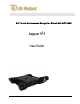
All-Terrain Autonomous Navigation Robot with GPS-IMU Jaguar V4 User Guide Copyright © 2013, Dr Robot Inc. All Rights Reserved. www.DrRobot.com V.03.09.
WARNINGS Do NOT power on the robot before reading and fully understanding the operation procedures explained in this manual. Always charge the battery when battery is running low or before storage. Always turn your robot off when not in use. Over-draining the battery (such as keeping the robot on without charging) will damage the battery. Never position your finger(s) in between the track and/or arm’s moving parts even when the power is off.
Copyright Statement This manual or any portion of it may not be copied or duplicated without the expressed written consent of Dr Robot. All the software, firmware, hardware and product design accompanying with Dr Robot’s product are solely owned and copyrighted by Dr Robot. End users are authorized to use for personal research and educational use only.
Table of Contents I. II. III. IV. V.
I. Specifications Jaguar V4 Mobile Robotic Platform is designed for indoor and outdoor applications requiring robust maneuverability and terrain maneuverability. It comes with four articulated arms and is fully wirelessly 802.11N connected. It integrates outdoor GPS and 9 DOF IMU (Gyro/Accelerometer/ Compass) for autonomous navigation. Jaguar V4 platform is rugged, light weight (< 30Kg), compact, weather and water resistant.
Temperature: -30° to +50° Shock resistant chassis Drop to concrete: Max: 600mm (2ft) Rated: 300mm (1ft) Motion and sensing controller (PWM, Position and Speed Control) 5Hz GPS and 9 DOF IMU (Gyro/Accelerometer/Compass) Laser scanner (5.6m, 4m or 30m) (Optional) Temperature sensing & Voltage monitoring Headlights Color Camera (640x480, 30fps) with audio WiFi802.
Jaguar Core Components JAGUARV4-ME Jaguar V4 Chassis (including motors and encoders) 1 PMS5005-JV4 Motion and Sensing Controller (Jaguar V4 Version) 1 WFS802G WiFi 802.11b/g Wireless Module 1 DMD2500 25A (peak 50A) Dual-channel DC Motor Driver Module 2 PMCHR12 DC-DC Power Board 1 AXCAM-A 640x480 Networked Color Camera (max. 30fps) with Two-Way Audio 1 OGPS501 Outdoor GPS Receiver with 5Hz Update Rate and WAAS 1 IMU9000 9 DOF IMU (Gyro/Accelerometer/Compass) 1 WRT802N 802.
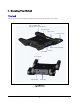
II. Knowing Your Robot Overlook The figure below illustrates the key components that you will identify on the Jaguar robot. GPS and 9 DOF IMU (Gyro/Accelerometer/Compass) Rear Arm-Track Drive-Track Front Arm-Track Laser Scanner (* Option) Headlights Camera Power Switch WiFi Antenna Handle Bar Jaguar Platform Copyright © 2013, Dr Robot Inc. All Rights Reserved. www.DrRobot.com -8- V.03.09.
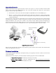
Operation Scenario Diagram below illustrates the typical operation scenario. The Jaguar is a wireless networked outdoor mobile robot. It comes with a wireless 802.11 AP/router. The remote host controller PC running the “Jaguar Control” program connects to the Jaguar robot via: Network cable – Connect the robot on-board AP/router.
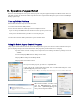
III. Operation of Jaguar Robot End user could develop his own Jaguar control program using the supplied development API and tools. Here, we will show you how to control the robot using the included “Jaguar Control Program” (You need to install Google Earth program first). Turn on/off the Platform Please follow the below steps to turn on the robot. 1. Turn the main switch to "ON" position. 2. Press the start button for a while (around 1 second) then release.
Google Earth is then loaded (this may take a while). Google Earth supports offline use (without Internet), but you have to obtain the map online ahead of use. When Internet is not presented, this loading process will take longer time when trying to connect with Google Earth website. You will not get the correct Latitude and Longitude position by clicking on map before the map loading is finished. When loaded, click “OK” button.
You could use the vertical track bar to zoom in or out. When the GPS-IMU module is presented, this program will connect and display the GPS information on Google Earth and IMU raw data on the 6 chart boxes. When camera is presented, the video and AV control buttons will be shown in the video window. You could use the included Gamepad controller to navigate the robot.
Camera display to full size Flip Jaguar forward Move arm to initial “0 o” (flat) position Move arms to “30o” (Tilt-up) position Set arm’s initial position Minimize camera display to original size Headlight On/OFF Flip Jaguar backward Jaguar Forward / Backward Control Jaguar Turning Control Rear Arm Up (fold in) Front Arm Up (fold in) Rear Arm Down (fold out) Front Arm Down (fold out) Gamepad Controller Note: when using Gamepad controller, you need to make sure the program window is in “focus”.
Battery information and motor information is displayed here. If the robot uses the included LiPo battery, you need to stop the robot when voltage is below marked voltage (22.2V) in order to prevent battery damage. Motor temperatures are also displayed here. “Encoder Pos” boxes show the encoder position values received in motor driver board from motion control board.
On normal program exit, Google Earth will be closed. However, you should double check using “Windows Task Manager”; otherwise, you may not be able to display Google Earth when you start Jaguar control program again. is to disable arm action. Copyright © 2013, Dr Robot Inc. All Rights Reserved. www.DrRobot.com - 15 - V.03.09.
Recharging Jaguar robot uses high performance LiPo batteries. Extreme caution is needed when dealing with this type of battery, explosion and damage could occur. Please read the Charge Station manual first and follow all the safety rules before proceeding further. 1) Turn off the robot 2) Loose the screws of Battery Box, disconnect the 2-Pin Tamiya connector and take the Battery Box out. 3) Power on the Charge Station. Use to make sure "LiPo BALANCE" is displayed on the LCD screen.
IV. Hardware and Electronics Network Settings Wireless Router Setting The included pre-configured wireless 802.11 B/G router has the following pre-set settings: SSID DriJaguar Router LAN 192.168.0.245 WEP 128bits Login ID admin KEY drrobotdrrobot Password drrobot Key Type Open Key Device Default Network Settings Note: The Ethernet modules are configured to serial-to-Ethernet mode in Jaguar platform. Ethernet Module 1 192.168.0.60 Port 1 Port Number 10001, UDP 115200.
Charging Plug Antenna Right Driving Motor Left Driving Motor OFF (Reserved) Arm Motor LiPo 22.2V 10AH Host Control PC ON Main Switch Motor Driver Board #1 Motor Driver Board #2 Gamepad Controller GPS Module Power 5V 3.3V Camera (AV) Power 5V Copyright © 2013, Dr Robot Inc. All Rights Reserved. www.DrRobot.com - 18 - V.03.09.
Motor Driver Board Two motor driver boards are used, one for the left and right track/wheel motors while the other one is for the arm motor. Input power Max current Input voltage H-Bridge 2 channels up to 25A continuous power per channel, peak up to 50A per channel for a few seconds 6~24V, 30V absolute max Motion and Sensing Controller This is a special version of PMS5005 board.
9 DOF IMU (Gyro, Accelerometer & Digital Compass) Input power Gyro Sensors Accelerometers Magnetic Compass Output Frequency 5V LY530ALH - 300o/s single-axis gyro LPR530ALH - 300 o/s dual-axis gyro 3 Axis ADXL345 13bit resolution Max +/-16G 3 Axis HMC5843 magnetometer 50Hz Output all sensor raw data and processed data by on-board MCU through serial port Laser Scanner Two laser scanner options are available, one with measurement range of 0.02-4m, and other one is 0.1-30m.
Powertrain (motor, speed-reducer and encoder) The following specifications are defined at the output shaft after speed-reduction, including the gearbox and /or pulley system. Arm shaft Track-arm motor (1 unit) Motor rated voltage Motor rated current Motor max current Shaft rated speed Shaft rated torque Shaft encoder resolution DC motor with steel gearbox 24V 2.75A 16A 19RPM 92Kg.
V. Further Development & Programming The Jaguar Control program The Jaguar Control program is written with Visual Studio 2008 express (in C#) under .Net 3.5 framework. You could download the development tools (Visual Studio 2008 express under .Net 3.5 framework) free from Microsoft. Please refer to the “Dr Robot Application Development Notes on C# Programming for Robot Control” for further information.
} You could read board voltage(5V) and battery voltage in standard sensor Event. private void myJaguar_StandardSensorEvent(object sender, EventArgs e) { boardVol = ((double) myJaguar.GetSensorBatteryAD1() / 4095 * 9); motVol = ((double) myJaguar.GetSensorBatteryAD2() / 4095 * 34.498); } You could read motor temperature in custom sensor event, function Trans2Temperature() is based on the sensor specification to translate AD value to temperature (in celcius degree).
myJaguar.DcMotorPositionTimeCtr(0, 2000, 2000); Using velocity control, move motor at encoder speed 200, you could use: myJaguar.DcMotorVelocityNonTimeCtrAll(200,NOCONTROL,NOCONTROL,NOCONTROL ,NOCONTROL,NOCONTROL); or myJaguar.DcMotorVelocityNonTimeCtr(0,200); For track/wheel motor control, we use differential-drive mode. Under this mode, PWM channel 3 is forward power and PWM 4 is turning power. To move forward with full power myJaguar.
It’s easier to read with a terminal program since the sensors’ measurements are reported in ASCII. DCM estimation and all measurements are delimited with “,”characters as well as a carriage return and line feed at the end of the data frame. Format: “$seq,accelX,accleY,accelZ,gyroY,gyroZ,gyroX,magnetomX,magnetomY,magnetomZ#” After “seq”, the data are raw AD value for each sensor.