
User Manual

www.seagullmodels.com
5
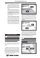
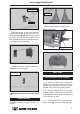
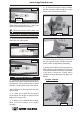
Attach the thread to the servo lead and
carefully thread it though the wing. Once you
have thread the lead throught the wing, remove
the string so it can use for the other servo
lead. Tape the servo lead to the wing to prevent
it from falling back into the wing.
Secure the servos with the screws pro-
vided with your radio system.
Repeat the procedure for the other wing
half.
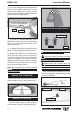
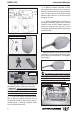
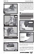
ENGINE MOUNT.
See pictures below ( Engine mount do not
include ) :
Mark and drill 4 holes for engine mount.
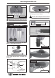
1) Using a modeling knife, carefully cut
off the rear portion of one of the 3 nylon tubes
leaving 1/2” protruding from the rear of the
stopper. This will be the fuel pick up tube.
2) Using a modeling knife, cut one length
of silicon fuel line. Connect one end of the line
to the weighted fuel pick up and the other end
to the nylon pick up tube.
3) Carefully bend the second nylon tube
up at a 45º angle. This tube is the vent tube.
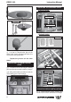
INSTALLING THE STOPPER ASSEMBLY.
FUEL TANK.
4x30mm.
Thread locker glue.
Electric wire.
Thread.
Wing bottom.