
Installation Guide
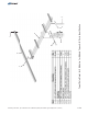
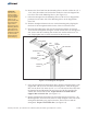
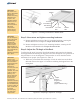

3 Bolt/8” x 1-3/4”
Flat Washer
Pivot Tab
Flat Washer
Lock Washer
Support Bar
3/8” Hex Nut
Figure 2-3: Securing Support Bar to Mounting Sleeve
CAUTION:
This is a two
person activity.
Module Rails are
long and unstable
before they are
fully secured to
the Strongback.
They must be held
in place by one
person while the
second person
aligns and
secures them to
the Strongback.
Failure to do so
could lead to
serious personal
injury.
5 of 9
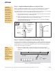
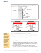
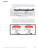
Figure 2-4: Tighten and Torque the Pivot Bolt
Strongback
Towers
No Gaps
No Gaps
Pivot
Bolt
Strongback
Towers
Visible
Gaps
Visible
Gaps
Pivot
Bolt
WRONG
CORRECT
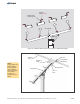
Step 3: Install the Module Rails to the Strongback
Module Rails run in an E-W direction and are secured to the mounting
angles using 3/8” x 1” bolts and hardware. There are four Module Rails to be installed.
Module Rails are installed differently depending on whether they are mounted
outboard or inboard on the Strongback. (See Figure 3-1)
A. Referring to Figure 3-1 for orientation of the outboard Module Rails, position
the first section of Module Rail. Align the Module Rail mounting holes with
the holes of the Strongback mounting angles and secure with 3/8” x 1” bolts
and hardware . Finger-tighten for
now.
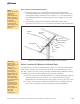
B. Now install the opposite outboard Module Rail f
. Refer to Figure 3-1 as needed for orientation of the Module Rail.
Strongback
; each Module Rail has two attachment points
(See also Figure 3-2)
ollowing the above
procedure
Start by installing the outboard sections of Module Rail first and work inward
Assembly Instructions, Top-of-Pole Mount for 8 Modules (TPM8) For Module Types A&B (Version 2, Rev E)