
Installation Guide

9 of 9
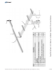
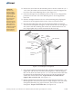
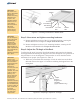
Figure 6-2: Setting the Tilt Angle
Elevation Set Points
Strongback
Support
Bar
65° 55° 45° 35° 25° 15°
B. Tilt the rack to the desired elevation angle (15°, 25°, 35°, 45°, 55°, or 65°)
and re-attach the Support Bar to the Strongback placing the 3/8” hardware in
the appropriate hole matching the desired elevation.
(See Figure 6-2)
Torque to 32-34 ft.-lbs.
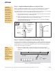
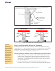
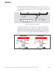
C. Re-tighten the Pivot Bolt. After changing the tilt angle and tightening the
Support Bar hardware, the Pivot Bolt must be re-tightened. The Pivot Bolt
cannot be left loose - the Mounting Sleeve Vertical Towers must be firmly
clamped to the sides of the Strongback eliminating any gaps between the
Vertical Towers and the Strongback. (See Figure
6-3)
Torque to 125-150 ft.-lbs.
Figure 6-3: Tighten and Torque the Pivot Bolt
Strongback
Towers
No Gaps
No Gaps
Pivot
Bolt
Strongback
Towers
Visible
Gaps
Visible
Gaps
Pivot
Bolt
WRONG
CORRECT
Assembly Instructions, Top-of-Pole Mount for 8 Modules (TPM8) For Module Types A&B (Version 2, Rev E)