
Installation Guide

NOTE:
Finger-tighten the
Module Rails to
the Cross-Bars
while installing.
After PV Modules
are installed,
re-tighten to
specified torque
values.
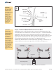
NOTE:
Double check the
orientation of
inboard to
outboard Module
Rails. If they are
installed differently
from these
instructions the
mounting holes
will not align to the
holes of the PV
Modules.
8 of 13
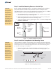
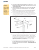
Start by installing the inboard sections of Module Rail first and work outward.
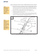
A. Referring to Figure 4-1 for orientation of the inboard Module Rails, position
the first section of Module Rail (with its angle cut end positioned north) at the
northern most position on the Cross-Bars. Align the Module Rail mounting
holes with the holes of the Cross-Bar mounting tabs and secure with 3/8” x 1”
bolts and hardware. Finger-tighten for now. (See also Figure 4-2)
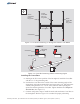
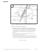
B. Install the next Module Rail creating a butt joint with the previously
installed Module Rail.
C. Position Module Rail with its angle cut end positioned south and its square
cut end butting up to the end of the previously installed Module Rail. Secure
with 3/8” x 1” bolts and hardware. Finger-tighten for now.
(See Figure 4-3)
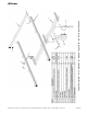
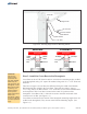
Figure 4-2: Installing the Northern-most inboard Module Rails to Cross-Bars
Module
Rail
Cross-Bars
Strongback
Beveled-End
Square-End
3/8” x 1” Bolt
Lock Washer
Flat Washer
Flat Washer
3/8” Nut
N
E
W
S
Assembly Instructions, Top-of-Pole Mount for 12 Modules (TPM12) For Module Types A, B & C (Version 2, Rev D)