
Installation Guide

B. Remove the Pivot Bolt from the Mounting Sleeve and collect the x 1-3/4”
bolt, flat washers and lock washer needed to secure the Support Bar to its Pivot
Tab on the Mounting Sleeve.
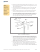
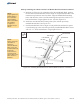
C. Orient the Strongback to the Mounting Sleeve with its Lower Support Bar
positioned on the same side of the Mounting Sleeve as the Support Bar
Pivot Tab.
D. Slide the Strongback between the two vertical mounting tabs, aligning the
thru-hole of the Strongback with the holes of the two Vertical Towers.
E. Insert the Pivot Bolt along with one flat washer through the one Vertical
Tower and the Strongback exiting the second Vertical Tower on the opposite
side. Secure with the remaining flat washer, lock washer and hex nut. For
now, finger tighten only to allow movement for the next step.
3/8”
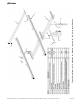
Figure 2-2: Installing the Strongback
NOTE:
Although this
system offers six
elevation set
points, for ease of
assembly, set the
angle to its lowest
setting of
15-degrees.
Optimum tilt
setting of the rack
will take place
later in these
instructions.
4 of 13
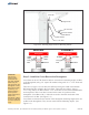
Strongback
Bolt
3/4” x 5-1/2”
Pivot
Flat
Washer
Vertical Towers
Flat
Washer
Lock Washer
3/4” Hex Nut
Mounting
Sleeve
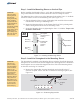
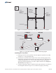
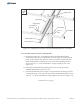
F. Pivot the Strongback and the Support Bar to align the mounting holes of the
Support Bar with its Pivot Tab on the Mounting Sleeve. Slide the Support
Bar over the Pivot Tab. Insert the 3/8” x 1-3/4” bolt and one flat washer thru
the Support Bar and Mounting Tab and secure it with the remaining flat
washer, lock washer and hex nut.
(See Figure 2-3)
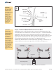
G. Return and tighten
Torque hardware on both ends of
Support Bar at 32-34 ft.-lbs.
the Pivot Bolt, Return and tighten the Pivot Bolt. The
Pivot Bolt cannot be left loose - the Mounting Sleeve Vertical Towers must
be firmly clamped to the sides of the Strongback eliminating any gaps
between the Vertical Towers and the Strongback.
(See Figure 2-4)
Torque to 125-150 ft.-lbs.
Assembly Instructions, Top-of-Pole Mount for 12 Modules (TPM12) For Module Types A, B & C (Version 2, Rev D)