
Installation Guide
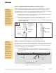


Start by installing the inboard sections of Module Rail first and work outward.
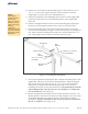
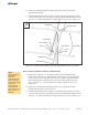
A. Referring to Figure 4-1 for orientation of the inboard Module Rails, position
the first section of Module Rail (with its angle cut end positioned north) at the
northern most position on the Cross-Bars. Align the Module Rail mounting
holes with the holes of the Cross-Bar mounting tabs and secure with 3/8” x 1”
bolts and hardware. Finger-tighten for now. (See also Figure 4-2)
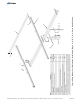
Cross-Bar
Module
Rail (in )Red
View looking North
Cross-Bar
Mounting Tab
Figure 4-1: Orientation of Module Rails to Cross-Bars
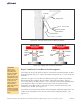
Figure 4-2: Installing the Northern-most Inboard Module Rails to Cross-Bars
NOTE:
Finger-tighten the
Module Rails to
the Cross-Bars
while installing.
After PV Modules
are installed,
re-tighten to
specified torque
values.
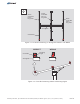
NOTE:
Double check the
orientation of
inboard to
outboard Module
Rails. If they are
installed differently
from these
instructions the
mounting holes
will not align to the
holes of the PV
Modules.
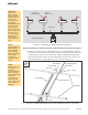
CAUTION:
This is a two
person activity.
Module Rails are
unstable before
they are fully
secured to the
Cross-Bars.
Module Rails must
be held in place
by one person
while the second
person aligns and
secures them to
the Cross-Bars.
Failure to do so
could lead to
serious personal
injury.
8 of 13
Module Rail
Cross-Bars
Strongback
Beveled-End
Square-End
3/8” x 1” Bolt
Lock Washer
Flat Washer
Flat Washer
3/8” Nut
N
E
W
S
Assembly Instructions, Top-of-Pole Mount for 10 Modules (TPM10) For Module Types C, D, E, F, & G, (Version 2, Rev E)