
Installation Guide


Installing the Cross-Bars.
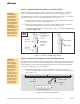
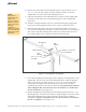
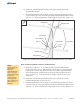
A. Starting at the N-S center position of the Strongback install the Cross-Bar
with the 3-1/2” long mounting tabs.
B. Position the Cross-Bar on the outside of the center mounting angle of the
Strongback. Align the mounting holes and secure using 3/8” flat and square
washers along with the 3/8” x 3-1/4” bolts and lock washer placing the
square flat washer against the Cross-Bar. Tighten hardware and
(See Figure 3-3)
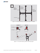
C. Continue using these steps to install the north and south most Cross-Bars to
the Strongback. Refer to figure 3-2 as needed for proper positioning.
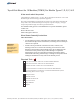
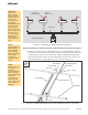
Module Rails run in an N-S direction and are secured to the mounting tabs of the
Cross-Bars (these are welded to the Cross-Bars) using 3/8” x 1” bolts and hardware.
Module Rails have different end configurations and must be installed with these
differences in mind. One end has an angle cut, while the other end is square cut.
The angled ends are oriented to the N-S outer edges of the rack while the square cut
is oriented inboard forming a butt joint between two Module Rail ends.
Additionally, Module Rails are installed differently depending on whether they are
mounted inboard or on the outer edges of the Cross-Bars. (See Figure 4-1)
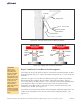
Torque to
30-32 ft.-lbs.
Step 4: Install the Module Rails to the Cross-Bars
CAUTION:
Be sure to place
the 3/8” square
washers on the
surface of the
Cross-Bar and not
the Mounting
Angles of the
Strongback.
Failure to do so
will damage the
surface of the
Cross-Bar when
the attaching
hardware is
tightened.
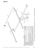
Figure 3-3: Installing Cross-Bars on the Strongback
7 of 13
N
E
W
S
Strongback
Cross-Bar
with 3-1/2” Tabs
Center
Mounting
Angle
3/8” Square
Washer
Flat Washer
Lock Washer
Flat Washer
3/8” Nut
3/8” x 3-1/4”
Bolt
Assembly Instructions, Top-of-Pole Mount for 10 Modules (TPM10) For Module Types C, D, E, F, & G, (Version 2, Rev E)