
Installation Guide


Step 1: Install the Mounting Sleeve on Vertical Pipe
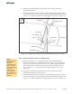
Step 2: Install the Strongback to the Mounting Sleeve
Before installing the Mounting Sleeve, verify that the Mounting Pole is plumb to
the ground and hasn't shifted or leaned while the concrete footing has cured.
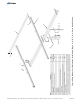
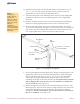
The Mounting Sleeve slips on top of the Mounting Pole and has four 1/2” Set Bolts
which are used to secure it to the Mounting Pole. (See Figure 1-1)
A. Slip the Mounting Sleeve on top of Mounting Pole and slide it down until it
rests/bottoms out on top of Mounting Pole.
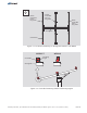
B. Rotate the Mounting Sleeve so that the Support Bar Pivot Tab is pointing
north and the Strongback Vertical Towers are leaning south.
C. Secure the Mounting Sleeve by tightening the four 1/2” Set Bolts.
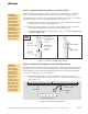
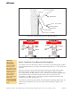
The Strongback is attached to the Mounting Sleeve using the Pivot Bolt that passes
through its two Vertical Towers and the Support Bar. The Support Bar is attached to
the Strongback on one end and the Support Bar Pivot Tab of the Mounting Sleeve
on the other end using 3/8” or 1/2” hardware.
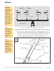
A. Remove the Support Bar from the Strongback and re-install in the 15
elevation set point. Secure with the hardware and finger tighten.
(See Figure 2-1)
Torque each
Set Bolt to 55-60 ft.-lbs.
°
3/8” or 1/2”
Figure 1-1: Installing the Mounting Sleeve
Figure 2-1: Positioning Support Bar
CAUTION:
Use care while
working around
the structure
during assembly.
There could be
components that
create hazards or
obstruct free
movement causing
serious bodily
injury. Many are at
head/eye level.
Move slowly and
with care around
the work area.
CAUTION:
This is a two
person activity.
The Strongback
must be held in
place by one
person while the
second person
aligns it and
secures it to the
Mounting Sleeve
using the Pivot
Bolt and the 1/2”
hardware. Failure
to do so could
lead to serious
personal injury.
3 of 13
Elevation Set Points
Strongback
Support
Bar
65° 55° 45° 35° 25° 15°
15° Position
N
E
W
S
Mounting
Sleeve
Strongback
Vertical Towers
Leaning
South
Support Bar
Pivot Tab
pointing
North
Mounting
Pole
Set Bolts
Set Bolts
Assembly Instructions, Top-of-Pole Mount for 10 Modules (TPM10) For Module Types C, D, E, F, & G, (Version 2, Rev E)