
Installation Guide


7 of 7
CAUTION:
Do not attempt to
remove the Pivot
Bolt during tilt
adjustments.
Removal could
lead to serious
personal injury or
death. Adjustments
are made with the
Pivot Bolt
hardware loosened
but in place.
CAUTION:
This is a two
person activity. As
the Pivot Bolt is
loosened and the
5/16” hardware is
removed, the rack
is heavy and
unstable. It must
be held in place
by one person
while the second
person loosens
and removes the
hardware and then
re-installs/tightens
the hardware back
in place. Failure to
do so could lead
to serious
personal injury
and damaged
components.
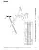
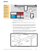
Figure 6-1: Preparing to Adjust the Tilt Angle
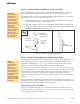
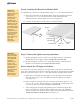
Figure 6-3: Re-Tighten and Torque the Pivot Bolt
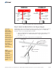
Figure 6-2: Setting the Elevation Angle
Mounting
Sleeve
Strongback
Pivot Plate
Lock Points
1
2
3
Lock Bolt
Location “A”
Lock Bolt
Location “B”
Vertical Tower
Elevation Set
Points
Lock Bolt Location
A
B
Lock
Point
1
45°
55°
2
25°
35°
3
5°
15°
Loosen
Pivot Bolt
(do not remove)
5/16” x 1” Lock Bolt
Flat Washer
Lock Washer
Pivot
Bolt
Lock
Bolt
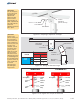
Vertical
Tower
Vertical
Tower
Strongback Strongback
Visible
Gap
No Gap
Visible
Gap
No Gap
WRONG CORRECT
Assembly Instructions, Top-of-Pole Mount for 1 Module (TPM1) For Module Types A, B, C, D, E, F, & G (Version 2, Rev D)