
Installation Guide
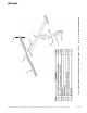


A. Remove the Pivot Bolt from the
Mounting Sleeve Vertical Tower.
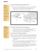
B. Position the Strongback to the Mounting Sleeve Vertical Tower as shown in
Figure 2-2.
C. Insert the Pivot Bolt along with one flat washer thru the Strongback Pivot
Plate and Vertical Tower. Secure with the flat washer, lock washer and hex
nut. For now, finger tighten only to allow movement for the next step.
D. Pivot the Strongback and align “Lock Bolt Location A” with “Lock Point
3”. Secure position by inserting 5/16” x 1” Lock Bolt, lock and flat and
washers into “Lock Point 3”.
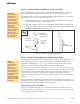
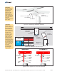
E.
and 5/16” x 1” Lock Bolt and washers
Tighten the Pivot Bolt. The Pivot Bolt cannot be left loose - the Mounting
Sleeve Vertical Tower must be firmly clamped to the side of the Strongback
eliminating any gaps between the Vertical Tower and the Strongback.
(See Figure 2-3)
Torque to 12-14 ft.-lbs.
Torque to 75-85 ft.-lbs.
4 of 7
CAUTION:
This is a two
person activity.
The Strongback
must be held in
place by one
person while the
second person
aligns it and
secures it to the
Mounting Sleeve
using the Pivot
Bolt and the 5/16”
Anchor Bolt.
Failure to do so
could lead to
serious personal
injury.
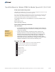
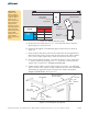
Figure 2-1: Setting Elevation Angle
Figure 2-2: Installing the Strongback
Mounting
Sleeve
Strongback
Pivot Plate
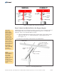
Lock Points
1
2
3
Lock Bolt
Location “A”
Lock Bolt
Location “B”
Vertical Tower
Elevation Set
Points
Lock Bolt Location
A
B
Lock
Point
1
45°
55°
2
25°
35°
3
5°
15°
Strongback
1
Bolt
/2” x 3/4”
Pivot
5
Bolt
/16” x 1”
Lock
Flat
Washer
Flat
Washer
Lock
Washer
Mounting Sleeve
Vertical Tower
Flat
Washer
Lock
Washer
½”
Hex Nut
Assembly Instructions, Top-of-Pole Mount for 1 Module (TPM1) For Module Types A, B, C, D, E, F, & G (Version 2, Rev D)