
Installation Guide
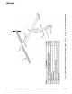
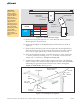

Step 1: Install the Mounting Sleeve on Vertical Pipe
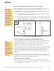
Step 2: Install the Strongback to the Mounting Sleeve
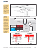
Before installing the Mounting Sleeve, verify that the Mounting Pole is plumb to
the ground and hasn't shifted or leaned while the concrete footing has cured.
The Mounting Sleeve slips on top of the Mounting Pole and has two 3/8” Set Bolts
which are used to secure it to the Mounting Pole.
A. Slip the Mounting Sleeve on top of Mounting Pole and slide it down until it
rests/bottoms out on top of Mounting Pole.
B. Rotate the Mounting Sleeve so the Strongback Vertical Tower is leaning south.
C. Secure the Mounting Sleeve by tightening the two 3/8” Set Bolts.
(See Figure 1-1)
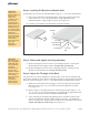
The Strongback gets attached to the Mounting Sleeve using a Pivot Bolt that passes
thorough the Vertical Tower of the Mounting Sleeve and the Pivot Plate of the
Strongback. Additionally, a 5/16” x 1” Lock Bolt is used to set the elevation and
further secure the Strongback to the Mounting Sleeve Vertical Tower.
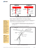
The system provides elevation set points of and does
so by the combination of two Lock Bolt Locations and three Lock Points. The Lock
Bolt Locations and accept the 5/16” x
1” Bolt. The Lock Points are located on the Strongback . Figure 2-1
shows the combinations of Lock Bolt Location to Lock Point and desired Elevation
Set Point.
As the Strongback is installed, the elevation is also temporarily set for purposes of
assembly. Once assembly is complete, the elevation angle will be reset based on the
preferred elevation angle of your particular installation.
For ease of assembly and safety, it is recommended that the elevation be set at 5°.
The table in Figure 2-1 shows that for a
Torque each
Set Bolt to 32-34 ft.-lbs.
5°, 15°, 25°, 35°, 45°, or 55°
are the threaded holes on the Vertical Tower
Pivot Plate
5° elevation the Lock Bolt Location would
be “A” and the Lock Point would be “3”.
Setting the Elevation Set Point
Figure 1-1: Installing the Mounting Sleeve
CAUTION:
Use care while
working around
the structure
during assembly.
There could be
components that
create hazards or
obstruct free
movement,
causing serious
bodily injury. Many
of these are at
head/eye level.
Move slowly and
with care around
the work area.
3 of 7
NOTE:
Although this
system offers six
elevation set
points, it is
recommended to
set the angle to its
lowest setting of
5-degrees for ease
of assembly.
Optimum tilt setting
of the rack will take
place later in these
instructions.
N
E
W
S
Mounting
Sleeve
Strongback
Vertical Tower
Leaning South
Set Bolts
pointing
North
Mounting
Pole
Set Bolts
Assembly Instructions, Top-of-Pole Mount for 1 Module (TPM1) For Module Types A, B, C, D, E, F, & G (Version 2, Rev D)