
Owner`s manual


01-01 Page 26 29863C
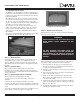
DV450S DIRECT VENT ROOM HEATER
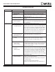
Problem: Possible Cause: Solutions:
Pilot will not Defective Magnet
Hold (Cont.). (mV Plus systems).
Defective Savety Magnet
Pilot Drops Pilot Orifice blocked. Replace Orifice with a new Orifice of the exact size and type.
Out. Wrong Pilot Orifice. Replace the Orifice with a new Orifice supplied specifically
for the appliance and gas in question.
No gas to Low gas pressure to Check Gas Pressure (7” N.G./11” L.P.)
Main Burner. appliance.
Pilot not lit. Light Pilot and wait for Thermo-generator to heat up
sufficiently to power the Main Operator. If Pilot fails to light,
hold, refer to the above sections.
Control Knob in Rotate “OFF/PILOT/ON” Control Knob to the “ON” position.
the “ON” position.
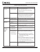
Thermostat/ Thermostat not in Turn Thermostat “ON” and then adjust Temperature Control
Wall Switch the “ON” position. to call for heat.
will not cycle
the Main Thermo-generator out- Refer to Item #7 in the Set-up Guide. If unable to meet
Burner. put voltage not within minimum requirements, replace the Thermo-generator.
design parameters.
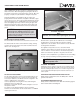
Defective Thermostat (A) With the Pilot adjusted properly, place a Jumper Wire
or Thermostat Wiring. between TPTH and TH. Take a mV reading across the
TPTH and TH Terminals of the Valve. This Closed Circuit
voltage should not fall below 300mV.
Record reading.
(B) Remove Jumper Wire from the TPTH and TH connections
and connect the Thermostat Wires to the same Terminals.
Closed Circuit voltage as described in the previous Step.
If the mV reading drops below150mV, excessive
resistance exists in the Thermostat Circuit and must be
isolated and eliminated.
Defective Wall Switch. Repeat the above troubleshooting items covered under
“Defective Thermostat or Thermostat Wiring” except,
TROUBLE SHOOTING (continued)
If the mV reading is above 6mV and the Safety Magnet
does not hold, replace the Valve.
(E) If Closed-Circuit mV reading is the same as the
Open-Circuit reading, the Coil is electrically “Open”.
Replace the Valve.
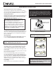
Verify operation of Safety Magnet in the following manner:
(A) Remove all Wires from the terminals of the Main Operator.
(B) Measure the electrical voltage between the Terminals
TPTH and TP. If the voltage is above 110mV and the
Safety Magnet does not hold, replace the Valve.