
Owner`s manual


DV450S DIRECT VENT ROOM HEATER
01-01 Page 21 29863C
Before operating this heater, please review the safety precau-
tions given on page 2 as well as the items listed below:
1. Check to make sure the logs are securely in place and
the rock wool, lava rock and Chunks have all been placed
correctly. (Refer to Steps 8 and 9.)
2. Check to see that all wiring is correct and enclosed to prevent
possible shock.
3. Check to ensure there are no gas leaks. This may be done
with a soap and water solution.
4. Make sure the glass is sealed and in its proper position.
Never operate this heater with the face removed or glass
removed or not sealed.
5. Verify that all venting and caps are unobstructed. Exhaust
gases are extremely hot. Check for obstructions from trees,
bushes, snow drifts, etc.
6. Read and understand these Instructions thoroughly before
attempting to operate this heater.
WARNING!
DO NOT OPERATE APPLIANCE WITH THE
PANEL(S) REMOVED, CRACKED OR BROKEN.
REPLACEMENT OF THE PANEL(S) SHOULD BE
DONE BY A LICENSED OR QUALIFIED SERVICE
PERSON.
Pre-Use Check List
Step 11 - Clean the Glass
To clean the glass, use a non-abrasive, mild cleaning solution.
(For example, a glass cleaner or for stubborn film, an oven
cleaner.) Apply an adequate amount to the glass and wipe off
with a damp cloth. Be sure all cleaner is thoroughly rinsed from
the glass.
Step 12 - Install the Glass
After cleaning the glass, carefully place the Glass Frame
Assembly onto the unit by positioning the tabs at the bottom of
the frame into the slots. Pull the latch releases forward and hook
over the glass frame.
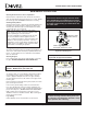
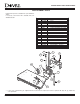
Step 13 - Optional Door Trim Kit Installation
The decorative trim can be installed at this time.
1. Lay the front face on a flat surface being careful not to
damage it.
2. Remove the lower shield by removing the (3) screws.
3. Lay the door trim onto the front face and put the shield back in
position and attach with the screws provided and those removed
earlier.
The screws are thread cutters and a power screwdriver is neces-
sary to drive the screws into position. See Figure 26.
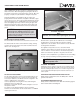
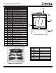
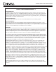
E. Adjustable Flue Restrictor
The DV450 has an adjustable flue restrictor for maximum per-
formance for vertical installations. The unit is shipped with the
restrictor in the open position and should be left open with any
horizontal installations.
The adjustment screw can be accessed by reaching through
the center air outlet slot at the top of the front face. See Figure
25. The slot of the screw head indicates the position of the
restrictor. See Figure 25. Turn the screw with a straight blade
screwdriver to close the restrictor as necessary.
The amount to close the restrictor will depend on the vent
height. If the vertical height is 20 feet or more, the restrictor
can be closed all the way. Anything less will require some
setting less than closed. The setting will vary depending on
the installation.
Any offsets in a vertical installation will restrict the system and
the flue restrictor will not need to be closed as much.
Figure 25 - Adjustable Flue Restrictor
Step 14 - Replacing the Front Face
Carefully lift the front face into position and replace the thumb
screw to hold it in position.
Figure 26 - Door Trim Installation
WARNING!
NEVER OPERATE THIS APPLIANCE WITH THE
DOOR AND/OR GLASS REMOVED OR NOT
SEALED.