
Owner`s manual


01-01 Page 20 29863C
DV450S DIRECT VENT ROOM HEATER
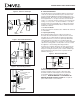
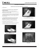
Figure 21 - Removal of Sealed Glass
Firebox Entry
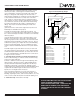
A. Removing the Front Face.
1. Losen the Thumb Screw from the bottom of the unit that holds
the Front Face in position. See Figure 20.
2. Carefully lift the Front Face up and pull the bottom forward.
Place in a safe place.
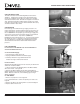
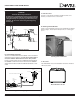
Figure 22 - Log Identification
D. Creating the Coal Bed Look.
Ember Chunks.
Randomly place the Ember Chunks on the Burner Pan between
and in line with the two front logs, creating a small wall of
embers. Do not allow the Chunks to cover the burner ports or air
holes in the Burner Pan as this may restrict air and/or gas flow,
creating a less than satisfactory performance. Too much restric-
tion can cause improper combustion and sooting (especially with
an appliance using propane gas). It is not necessary to use all of
the Chunks supplied with the unit.
Once the Burner Pan has been correctly covered with Ember
Chunks, place a single row of ember Chunks on the ember tray
located at the front of the Log Assembly.
Once the Ember Chunks are in place, a thin layer of Mineral Wool
may be bridged over the Chunks for greater enhancement.
B. Removing the Glass.
3. Remove the Glass Frame Assembly by pulling the Latch
Releases forward and upward. See Figure 21. Lift the Glass
Frame Assembly up, sliding the [3] tabs at the bottom out of
the slots.
Lava Rock.
Distribute the lava rock over the surface of the hearth pan next
to the glass being careful not get lava rock down into the air
inlet slots or onto the surface of the Burner Pan. The lava rock
does not change the flame and does not have to be used. A
different look to to the front of the unit is to add a row of ember
Chunks.
C. Log Placement.
The logs are shipped in separate packaging. Refer to Fig. 22 for
identification for the installation process.
Figure 20 - Bottom Thumb Screw
REAR LOG
LEFT
TWIG
RIGHT
TWIG
LEFT LOG
RIGHT LOG
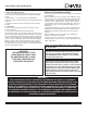
1. Place rear log over two white pins on the firebox floor at the
back of firebox. See Fig. 23.
2. Set left log over two pins on left side of firebox floor. Fig. 24.
3. Set right log over two pins on right side of firebox floor.
4. Set left twig over one pin on top left of rear log and into groove
on front left log.
5. Set right twig over two pins on top right of rear log and into
groove on front right log.
Figure 23
Rear Log
Placement
Figure 24
Left and Right
Log Placement