
Owner`s manual


DV450S DIRECT VENT ROOM HEATER
01-01 Page 19 29863C
WARNING!
Electrical Grounding Instructions
This appliance is equipped with a three-prong (grounding)
plug for your protection against shock hazard and should
be plugged directly into a properly grounded three-prong
receptacle. Do not cut or remove the grounding prong
from this plug.
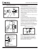
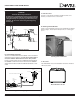
Blower Wiring Diagram
Figure 12 - Wiring Diagram
B. Optional Wall Thermostat
The use of a millivolt Thermostat is allowed. It must be located
within 20 feet of the appliance. In order for the Thermostat to
work, the “ON/OFF” Switch must be in the “ON” position.
Figure 12 shows how to connect a millivolt Thermostat without
the “ON/OFF” Switch in the Circuit. Disconnect the “ON/OFF”
Switch from the Valve and wire the millivolt Thermostat as indi-
cated.
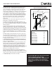
20613 (1)
14212 (1)
25385 (1)
25579 (1)
25580 (1)
28749 (1)
18164 (1)
23998 (1)
Rocker Switch / Wall Thermostat / Remote
Variable
Regulator
Pilot
Adjustment
Cap
Manifold Pressure
Inlet Pressure
Push Button
Ignitor
Ignitor
Thermopile
Pilot
Thermocouple
C. Remote Control
A remote control thermostat may be installed on this stove.
Contact your dealer for the correct model.
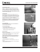
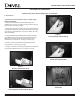
D. Warming Shelves/Brackets
Please see the Installation Instructions included with the Shelves.
Refer to page 5, Heater System Components, for ordering pur-
poses.
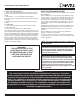
E. Door Trim
Part # 844-0140. Please the Installation Instructions included
with the Door Trim.
Warming Shelf and Bracket
Decorative Glass Accent