
Owner`s manual


01-01 Page 18 29863C
DV450S DIRECT VENT ROOM HEATER
OPTIONAL ACCESSORIES
A. Optional Fan
Blower Installation:
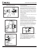
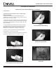
1. Remove the Knockout Plate from the Backshield of the
DV450S by prying out on the plate and clip or break the tabs that
hold it in place. See Figure 1 below.
2. Remove the tape from the back of the strip of Gasket Material
included with the blower kit, and position the Gasket over the edge
of the opening of the Backshield. See Figure 2 below. (This will
eliminate vibration.)
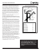
3. Install the Blower into the Backshield by hooking the bottom
of the Blower Housing into the opening and rock the top of the
Blower forward. Fasten the blower in place with the screws
included in the Fastener Pack. See Figure 3 on this page.
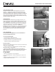
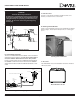
4. Attach the Switch Control Box on the Backshield with the
screws provided. See Figure 4, this page.
5. Plug the Connector on the wiring assembly into the Receptacle
on the top of the Blower Housing. See Figure 5, this page.
Figure 1
Removal of Knockout Plate
Figure 2
Placing Blower Gasket on Back Shield
Figure 3
Fan Installation on Back Shield
Figure 4
Attach Switch Control Box
Receptacle
Blower
Control
Box
Figure 5
Receptacle
The Optional Fan Kit (844-0150) requires a 110VAC supply.
Optional accessories may be added now or at a later date.