
Owner`s manual


01-01 Page 14 29863C
DV450S DIRECT VENT ROOM HEATER
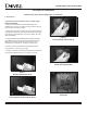
C. Existing Masonry Chimney Installation
This installation is subject to local jurisdiction. Some codes
may require the use of another liner for intake air. If so, the
4” aluminum liner should be inside a 6” UL 181 listed liner.
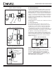
This Heater can be vented through an existing Masonry Chimney
but the chimney must be lined with one UL 1777 listed 4” alumi-
num flexible gas vent liner for exhaust. The existing Flue will
be used to supply the air intake to the galvanized steel Flue
system. See Figure 11. Before installing the liner system, the
chimney passageway should be cleaned and examined to
verify it is unobstructed and in good structural condition.
Measure and record the chimney dimensions to determine total
flexible liner requirements.
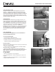
Follow the liner manufacturer’s instructions for installing the liner
in the chimney. Attach a flexible liner puller to the liner and secure
a rope to the puller. One person should feed the liner through
the chimney, and another person should pull the liner from the
bottom, with the rope, guiding the liner down the chimney. After
feeding the liner down the chimney, form a 90˚ angle and bring
the liner through the hole in the chimney wall. (If running two
liners, run the 6” liner first and then the 4” inside of it.) Extend the
liner through the wall of the chimney and attach it to the venting
system extending from the top of the Heater.
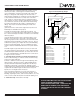
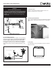
Construct a metal flashing large enough and strong enough
to cover the chimney opening and support the Heater Vertical
Termination Cap. The flashing needs to fold down over and
around the outside of the masonry chimney so that it can be
secured to the chimney by 4 screws. See Figure 12. The
flashing will require a hole at least 6
1
/
2
'' in diameter. (If using a
6” liner, extend the 6'' flexible liner through the flashing and attach
it to the VTA (Vertical Termination Adapter) with screws provided.)
Secure the VTA to the flashing with the screws provided and seal
the VTA/Flashing joint with a silicone sealant to prevent moisture
from running down the liner into the chimney.
Attach the 4'' gas vent liner to the Vertical Termination Cap with
screws provided, then attach the Termination Cap to the VTA with
screws provided. See Figure 12.
Figure 11
Adaptation to Masonry Chimney
WALL THIMBLE/
TRIM COLLAR
INSIDE CHIMNEY
DIAMETER
6" MINIMUM
4'' UL 1777 LISTED
GAS VENT INNER
FLEX LINER
24" MINIMUM
VERTICAL HEIGHT
DURA-VENT GS
VENTING
6"
INTAKE AIR
EXHAUST
SEAL WITH SILICONE
SEAL WITH SILICONE
Figure 12
Masonry Termination
RIGID FLASHING
(ATTACHED TO CHIMNEY
WITH SCREWS WITH
SILICONE SEALANT
UNDERNEATH)
SILICONE SEALANTVTA
6" LINER (OPTIONAL)
WARNING
WHEN VENT SECTIONS EXCEEDING 3 FEET IN
LENGTH ARE INSTALLED BETWEEN AN OFFSET/
RETURN, STRUCTURAL SUPPORT MUST BE
PROVIDED TO REDUCE OFF-CENTER LOADING AND
PREVENT VENT SECTIONS FROM SEPARATING AT
THE VENT JOINTS.